

5.5 Study on Optimization of Parameters of Measuring Path …
401
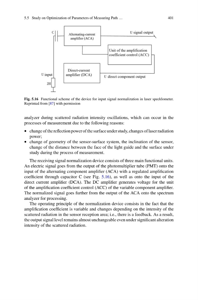
Fig. 5.16 Functional scheme of the device for input signal normalization in laser specklometer.
Reprinted from [87] with permission
analyzer during scattered radiation intensity oscillations, which can occur in the
processes of measurement due to the following reasons:
• change of the reflection power of the surface under study, changes of laser radiation
power;
• change of geometry of the sensor-surface system, the inclination of the sensor,
change of the distance between the face of the light guide and the surface under
study during the process of measurement.
The receiving signal normalization device consists of three main functional units.
An electric signal goes from the output of the photomultiplier tube (PMT) onto the
input of the alternating component amplifier (ACA) with a regulated amplification
coefficient through capacitor C (see Fig. 5.16), as well as onto the input of the
direct current amplifier (DCA). The DC amplifier generates voltage for the unit
of the amplification coefficient control (ACC) of the variable component amplifier.
The normalized signal goes further from the output of the ACA onto the spectrum
analyzer for processing.
The operating principle of the normalization device consists in the fact that the
amplification coefficient is variable and changes depending on the intensity of the
scattered radiation in the sensor reception area; i.e., there is a feedback. As a result,
the output signal level remains almost unchangeable even under significant alteration
intensity of the scattered radiation.
401
Fig. 5.16 Functional scheme of the device for input signal normalization in laser specklometer.
Reprinted from [87] with permission
analyzer during scattered radiation intensity oscillations, which can occur in the
processes of measurement due to the following reasons:
• change of the reflection power of the surface under study, changes of laser radiation
power;
• change of geometry of the sensor-surface system, the inclination of the sensor,
change of the distance between the face of the light guide and the surface under
study during the process of measurement.
The receiving signal normalization device consists of three main functional units.
An electric signal goes from the output of the photomultiplier tube (PMT) onto the
input of the alternating component amplifier (ACA) with a regulated amplification
coefficient through capacitor C (see Fig. 5.16), as well as onto the input of the
direct current amplifier (DCA). The DC amplifier generates voltage for the unit
of the amplification coefficient control (ACC) of the variable component amplifier.
The normalized signal goes further from the output of the ACA onto the spectrum
analyzer for processing.
The operating principle of the normalization device consists in the fact that the
amplification coefficient is variable and changes depending on the intensity of the
scattered radiation in the sensor reception area; i.e., there is a feedback. As a result,
the output signal level remains almost unchangeable even under significant alteration
intensity of the scattered radiation.