

5.5 Study on Optimization of Parameters of Measuring Path …
399
Piezoelectric, magnetic pickups and capacitive microphones, which are applicable
of measuring of oscillation amplitude of ultrasonic transducer, are contact. They are
sensitive to background impact in industry conditions and do not provide sufficient
accuracy and spatial distribution during measurements.
Application of laser interferometers gives the possibility to avoid the abovementioned disadvantages, but their usage for control of USWS oscillation amplitude
requires additional treatment of the surface of the instrument to make it mirror. The
structural–functional scheme of the laboratory prototype of the laser specklometer
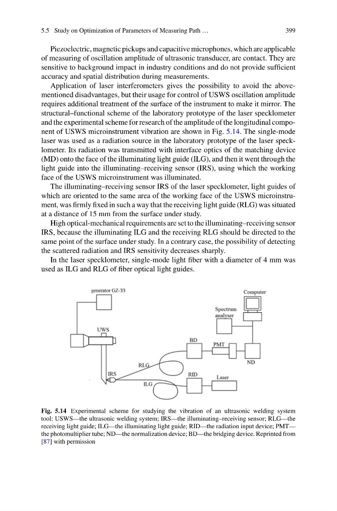
and the experimental scheme for research of the amplitude of the longitudinal component of USWS microinstrument vibration are shown in Fig. 5.14. The single-mode
laser was used as a radiation source in the laboratory prototype of the laser specklometer. Its radiation was transmitted with interface optics of the matching device
(MD) onto the face of the illuminating light guide (ILG), and then it went through the
light guide into the illuminating–receiving sensor (IRS), using which the working
face of the USWS microinstrument was illuminated.
The illuminating–receiving sensor IRS of the laser specklometer, light guides of
which are oriented to the same area of the working face of the USWS microinstrument, was firmly fixed in such a way that the receiving light guide (RLG) was situated
at a distance of 15 mm from the surface under study.
High optical-mechanical requirements are set to the illuminating–receiving sensor
IRS, because the illuminating ILG and the receiving RLG should be directed to the
same point of the surface under study. In a contrary case, the possibility of detecting
the scattered radiation and IRS sensitivity decreases sharply.
In the laser specklometer, single-mode light fiber with a diameter of 4 mm was
used as ILG and RLG of fiber optical light guides.
Fig. 5.14 Experimental scheme for studying the vibration of an ultrasonic welding system
tool: USWS—the ultrasonic welding system; IRS—the illuminating–receiving sensor; RLG—the
receiving light guide; ILG—the illuminating light guide; RID—the radiation input device; PMT—
the photomultiplier tube; ND—the normalization device; BD—the bridging device. Reprinted from
[87] with permission
399
Piezoelectric, magnetic pickups and capacitive microphones, which are applicable
of measuring of oscillation amplitude of ultrasonic transducer, are contact. They are
sensitive to background impact in industry conditions and do not provide sufficient
accuracy and spatial distribution during measurements.
Application of laser interferometers gives the possibility to avoid the abovementioned disadvantages, but their usage for control of USWS oscillation amplitude
requires additional treatment of the surface of the instrument to make it mirror. The
structural–functional scheme of the laboratory prototype of the laser specklometer
and the experimental scheme for research of the amplitude of the longitudinal component of USWS microinstrument vibration are shown in Fig. 5.14. The single-mode
laser was used as a radiation source in the laboratory prototype of the laser specklometer. Its radiation was transmitted with interface optics of the matching device
(MD) onto the face of the illuminating light guide (ILG), and then it went through the
light guide into the illuminating–receiving sensor (IRS), using which the working
face of the USWS microinstrument was illuminated.
The illuminating–receiving sensor IRS of the laser specklometer, light guides of
which are oriented to the same area of the working face of the USWS microinstrument, was firmly fixed in such a way that the receiving light guide (RLG) was situated
at a distance of 15 mm from the surface under study.
High optical-mechanical requirements are set to the illuminating–receiving sensor
IRS, because the illuminating ILG and the receiving RLG should be directed to the
same point of the surface under study. In a contrary case, the possibility of detecting
the scattered radiation and IRS sensitivity decreases sharply.
In the laser specklometer, single-mode light fiber with a diameter of 4 mm was
used as ILG and RLG of fiber optical light guides.
Fig. 5.14 Experimental scheme for studying the vibration of an ultrasonic welding system
tool: USWS—the ultrasonic welding system; IRS—the illuminating–receiving sensor; RLG—the
receiving light guide; ILG—the illuminating light guide; RID—the radiation input device; PMT—
the photomultiplier tube; ND—the normalization device; BD—the bridging device. Reprinted from
[87] with permission