

254
3 Holographic Interferometry for Studying …
localization surface;
r r is the position vector on the hologram surface; δ xob1 , δ yob1 ,
δ xref1 , δ yref1 are the initial phases of E x and E y components of object and reference
waves.
Equation (3.68) contain full information about the state of object wave polarization, and using this method of hologram recording and reconstruction, the shift of
the interference fringes is proportional to the quantity of their polarization parameter changing. And the phase differences ϕ 1 = ϕ 2x − ϕ 1x and ϕ 2 = ϕ 2y − ϕ 1y
occurring between object waves are conditioned by the change of not only illumination direction, wavelength and coordinates of object points, but also by the change of
polarization parameters tgϕ = A 1 /B 1 and δ ob1 = δ xob1
−
δ yob1 . Using this fact on the
changes in polarization parameters of each pair of reconstructed waves, it is possible
to determine either the direction of change of the surface shape under its contouring
or shift direction of surface points during investigation of its deformations and shifts.
From (3.68), the formulae follow, which connect the quantity and direction of the
relief surface as well the quantity and the direction of shifts of the surface points
with polarization characteristics of the resulting object wave. For example, while
investigating the shape of the surface, it is necessary to set parameter change of the
illuminating wave
k 1 and while investigating the shift points—change of coordinates
of object surface points
r ob1 . It is possible to implement combined methods to increase
sensitivity and to broaden the measurement range.
Another method for detecting the quantity and direction of relative shift is a
method based on introduction of set phase shifts in one of the reference waves. For
its implementation, it is also necessary to use two spatially separated reference waves
during recording and reconstruction. An optical path-altering device is inserted in one
of the waves, for example, a compensator. Alteration of the length of the compensator
leads to interference fringes shift in the observed interference pattern. By increasing
or decreasing the phase difference at a certain quantity, the direction of relative shifts
of points on the surface under study can be determined according to the shift direction
of interference fringes. For example, let ϕ > 0 and the phase shift δ be inserted
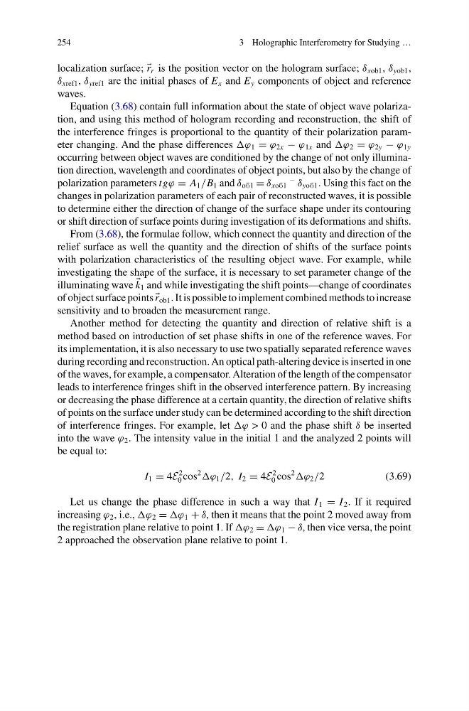
into the wave ϕ 2 . The intensity value in the initial 1 and the analyzed 2 points will
be equal to:
I 1 = 4E
2
0 cos
2
ϕ 1 /2, I 2 = 4E
2
0 cos
2
ϕ 2 /2
(3.69)
Let us change the phase difference in such a way that I 1 = I 2 . If it required
increasing ϕ 2 , i.e., ϕ 2 = ϕ 1 + δ, then it means that the point 2 moved away from
the registration plane relative to point 1. If ϕ 2 = ϕ 1 − δ, then vice versa, the point
2 approached the observation plane relative to point 1.
3 Holographic Interferometry for Studying …
localization surface;
r r is the position vector on the hologram surface; δ xob1 , δ yob1 ,
δ xref1 , δ yref1 are the initial phases of E x and E y components of object and reference
waves.
Equation (3.68) contain full information about the state of object wave polarization, and using this method of hologram recording and reconstruction, the shift of
the interference fringes is proportional to the quantity of their polarization parameter changing. And the phase differences ϕ 1 = ϕ 2x − ϕ 1x and ϕ 2 = ϕ 2y − ϕ 1y
occurring between object waves are conditioned by the change of not only illumination direction, wavelength and coordinates of object points, but also by the change of
polarization parameters tgϕ = A 1 /B 1 and δ ob1 = δ xob1
−
δ yob1 . Using this fact on the
changes in polarization parameters of each pair of reconstructed waves, it is possible
to determine either the direction of change of the surface shape under its contouring
or shift direction of surface points during investigation of its deformations and shifts.
From (3.68), the formulae follow, which connect the quantity and direction of the
relief surface as well the quantity and the direction of shifts of the surface points
with polarization characteristics of the resulting object wave. For example, while
investigating the shape of the surface, it is necessary to set parameter change of the
illuminating wave
k 1 and while investigating the shift points—change of coordinates
of object surface points
r ob1 . It is possible to implement combined methods to increase
sensitivity and to broaden the measurement range.
Another method for detecting the quantity and direction of relative shift is a
method based on introduction of set phase shifts in one of the reference waves. For
its implementation, it is also necessary to use two spatially separated reference waves
during recording and reconstruction. An optical path-altering device is inserted in one
of the waves, for example, a compensator. Alteration of the length of the compensator
leads to interference fringes shift in the observed interference pattern. By increasing
or decreasing the phase difference at a certain quantity, the direction of relative shifts
of points on the surface under study can be determined according to the shift direction
of interference fringes. For example, let ϕ > 0 and the phase shift δ be inserted
into the wave ϕ 2 . The intensity value in the initial 1 and the analyzed 2 points will
be equal to:
I 1 = 4E
2
0 cos
2
ϕ 1 /2, I 2 = 4E
2
0 cos
2
ϕ 2 /2
(3.69)
Let us change the phase difference in such a way that I 1 = I 2 . If it required
increasing ϕ 2 , i.e., ϕ 2 = ϕ 1 + δ, then it means that the point 2 moved away from
the registration plane relative to point 1. If ϕ 2 = ϕ 1 − δ, then vice versa, the point
2 approached the observation plane relative to point 1.