

3.3 Laser-Holographic Complex …
253
According to the conducted analysis in common case the localization surface
of the interference pattern does not coincide with the surface of the object under
study; and in the case of gradual shifts of (3.64), it is placed in the infinity. But it is
supposed that mainly deformation shifts will present during the study of the point
shifts of human chest; i.e., the localization surface will be near the object under study.
3.3.4 Methods of Estimating the Shift Value of Points
on the Surface of the Object Under Study Considering
the Direction of Shifts
Let us suggest several methods for estimating the direction of shifts. For implementation of these methods it is necessary to use two spatially separated light beams for
recording and reconstructing of holograms. Separating of reference beams can be
conducted in different ways, for example, using KDP crystal (Pockels or Kerr cell)
and the beam splitter, and in each of the reference beams the polarizers are installed,
which are crossed between each other. In this case, holograms will be recorded and
reconstructed by two mutually orthogonal polarized waves.
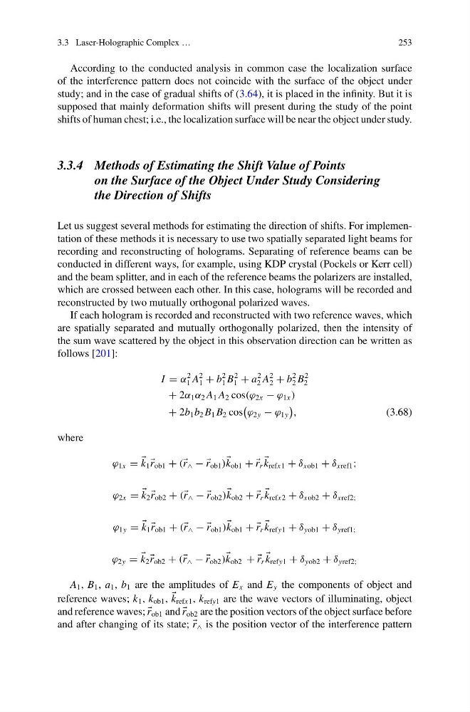
If each hologram is recorded and reconstructed with two reference waves, which
are spatially separated and mutually orthogonally polarized, then the intensity of
the sum wave scattered by the object in this observation direction can be written as
follows [201]:
I = α
2
1 A
2
1 + b
2
1 B
2
1 + a
2
2 A
2
2 + b
2
2 B
2
2
+ 2α 1 α 2 A 1 A 2 cos(ϕ 2x − ϕ 1x )
+ 2b 1 b 2 B 1 B 2 cos
ϕ 2y − ϕ 1y
,
(3.68)
where
ϕ 1x =
k 1
r ob1 + ( r ∧ − −
r ob1 )
k ob1 + +
r r
k refx1 + δ xob1 + δ xref1 ;
ϕ 2x =
k 2
r ob2 + ( r ∧ − −
r ob2 )
k ob2 + +
r r
k refx2 + δ xob2 + δ xref2;
ϕ 1y =
k 1
r ob1 + ( r ∧ − −
r ob1 )
k ob1 + +
r r
k refy1 + δ yob1 + δ yref1;
ϕ 2y =
k 2
r ob2 + ( r ∧ − −
r ob2 )
k ob2 + +
r r
k refy1 + δ yob2 + δ yref2;
A 1 , B 1 , a 1 , b 1 are the amplitudes of E x and E y the components of object and
reference waves; k 1 , k ob1 ,
k refx1 , k refy1 are the wave vectors of illuminating, object
and reference waves;
r ob1 and
r ob2 are the position vectors of the object surface before
and after changing of its state;
r ∧ is the position vector of the interference pattern
253
According to the conducted analysis in common case the localization surface
of the interference pattern does not coincide with the surface of the object under
study; and in the case of gradual shifts of (3.64), it is placed in the infinity. But it is
supposed that mainly deformation shifts will present during the study of the point
shifts of human chest; i.e., the localization surface will be near the object under study.
3.3.4 Methods of Estimating the Shift Value of Points
on the Surface of the Object Under Study Considering
the Direction of Shifts
Let us suggest several methods for estimating the direction of shifts. For implementation of these methods it is necessary to use two spatially separated light beams for
recording and reconstructing of holograms. Separating of reference beams can be
conducted in different ways, for example, using KDP crystal (Pockels or Kerr cell)
and the beam splitter, and in each of the reference beams the polarizers are installed,
which are crossed between each other. In this case, holograms will be recorded and
reconstructed by two mutually orthogonal polarized waves.
If each hologram is recorded and reconstructed with two reference waves, which
are spatially separated and mutually orthogonally polarized, then the intensity of
the sum wave scattered by the object in this observation direction can be written as
follows [201]:
I = α
2
1 A
2
1 + b
2
1 B
2
1 + a
2
2 A
2
2 + b
2
2 B
2
2
+ 2α 1 α 2 A 1 A 2 cos(ϕ 2x − ϕ 1x )
+ 2b 1 b 2 B 1 B 2 cos
ϕ 2y − ϕ 1y
,
(3.68)
where
ϕ 1x =
k 1
r ob1 + ( r ∧ − −
r ob1 )
k ob1 + +
r r
k refx1 + δ xob1 + δ xref1 ;
ϕ 2x =
k 2
r ob2 + ( r ∧ − −
r ob2 )
k ob2 + +
r r
k refx2 + δ xob2 + δ xref2;
ϕ 1y =
k 1
r ob1 + ( r ∧ − −
r ob1 )
k ob1 + +
r r
k refy1 + δ yob1 + δ yref1;
ϕ 2y =
k 2
r ob2 + ( r ∧ − −
r ob2 )
k ob2 + +
r r
k refy1 + δ yob2 + δ yref2;
A 1 , B 1 , a 1 , b 1 are the amplitudes of E x and E y the components of object and
reference waves; k 1 , k ob1 ,
k refx1 , k refy1 are the wave vectors of illuminating, object
and reference waves;
r ob1 and
r ob2 are the position vectors of the object surface before
and after changing of its state;
r ∧ is the position vector of the interference pattern