

3.3 Laser-Holographic Complex …
251
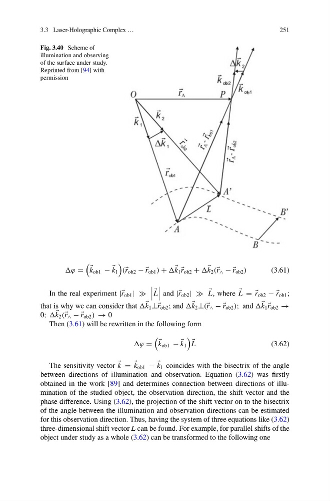
Fig. 3.40 Scheme of
illumination and observing
of the surface under study.
Reprinted from [94] with
permission
ϕ =
k ob1 −
k 1
( r ob2 − −
r ob1 ) +
k 1
r ob2 +
k 2 ( r ∧ − −
r ob2 )
(3.61)
In the real experiment || r ob1 | |
L
and || r ob2 | |
L, where
L = =
r ob2 − −
r ob1 ;
that is why we can consider that
k 1 ⊥⊥ r ob2 ; and
k 2 ⊥( r ∧ − −
r ob2 ); and
k 1
r ob2 →
0;
k 2 ( r ∧ − −
r ob2 ) → 0
Then (3.61) will be rewritten in the following form
ϕ =
k ob1 −
k 1
L
(3.62)
The sensitivity vector
k =
k ob1 −
k 1 coincides with the bisectrix of the angle
between directions of illumination and observation. Equation (3.62) was firstly
obtained in the work [89] and determines connection between directions of illumination of the studied object, the observation direction, the shift vector and the
phase difference. Using (3.62), the projection of the shift vector on to the bisectrix
of the angle between the illumination and observation directions can be estimated
for this observation direction. Thus, having the system of three equations like (3.62)
three-dimensional shift vector L can be found. For example, for parallel shifts of the
object under study as a whole (3.62) can be transformed to the following one
251
Fig. 3.40 Scheme of
illumination and observing
of the surface under study.
Reprinted from [94] with
permission
ϕ =
k ob1 −
k 1
( r ob2 − −
r ob1 ) +
k 1
r ob2 +
k 2 ( r ∧ − −
r ob2 )
(3.61)
In the real experiment || r ob1 | |
L
and || r ob2 | |
L, where
L = =
r ob2 − −
r ob1 ;
that is why we can consider that
k 1 ⊥⊥ r ob2 ; and
k 2 ⊥( r ∧ − −
r ob2 ); and
k 1
r ob2 →
0;
k 2 ( r ∧ − −
r ob2 ) → 0
Then (3.61) will be rewritten in the following form
ϕ =
k ob1 −
k 1
L
(3.62)
The sensitivity vector
k =
k ob1 −
k 1 coincides with the bisectrix of the angle
between directions of illumination and observation. Equation (3.62) was firstly
obtained in the work [89] and determines connection between directions of illumination of the studied object, the observation direction, the shift vector and the
phase difference. Using (3.62), the projection of the shift vector on to the bisectrix
of the angle between the illumination and observation directions can be estimated
for this observation direction. Thus, having the system of three equations like (3.62)
three-dimensional shift vector L can be found. For example, for parallel shifts of the
object under study as a whole (3.62) can be transformed to the following one