

250
3 Holographic Interferometry for Studying …
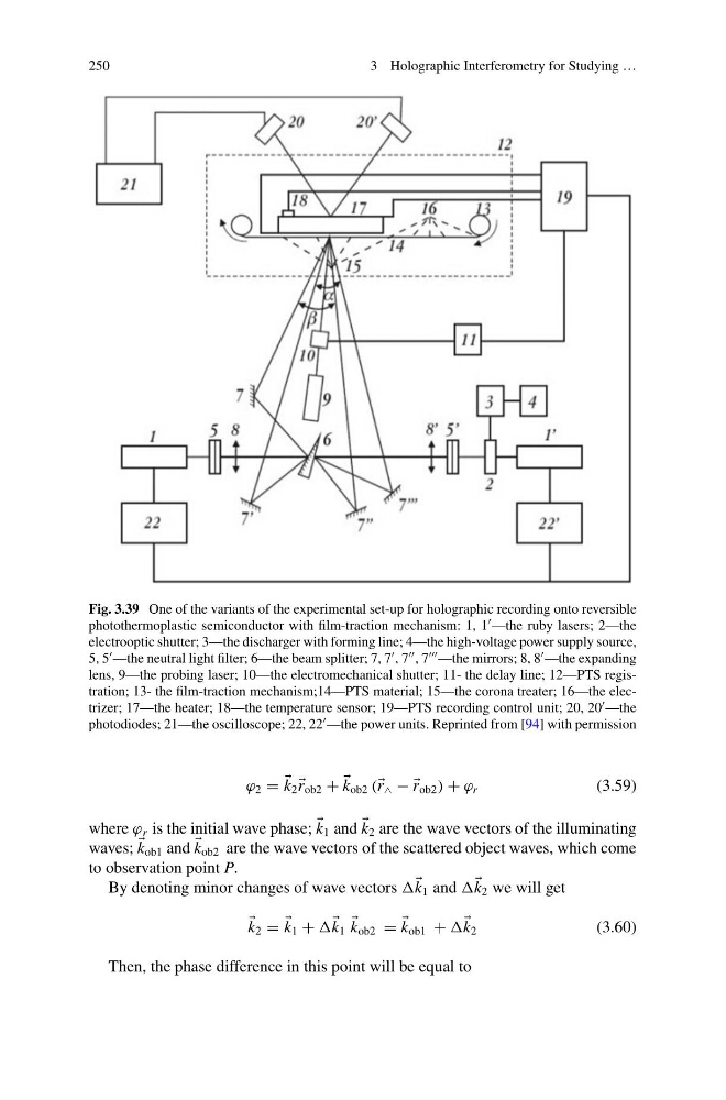
Fig. 3.39 One of the variants of the experimental set-up for holographic recording onto reversible
photothermoplastic semiconductor with film-traction mechanism: 1, 1 —the ruby lasers; 2—the
electrooptic shutter; 3—the discharger with forming line; 4—the high-voltage power supply source,
5, 5 —the neutral light filter; 6—the beam splitter; 7, 7 , 7 , 7 —the mirrors; 8, 8 —the expanding
lens, 9—the probing laser; 10—the electromechanical shutter; 11- the delay line; 12—PTS registration; 13- the film-traction mechanism;14—PTS material; 15—the corona treater; 16—the electrizer; 17—the heater; 18—the temperature sensor; 19—PTS recording control unit; 20, 20 —the
photodiodes; 21—the oscilloscope; 22, 22 —the power units. Reprinted from [94] with permission
ϕ 2 =
k 2
r ob2 +
k ob2 ( r ∧ − −
r ob2 ) + ϕ r
(3.59)
where ϕ r is the initial wave phase;
k 1 and
k 2 are the wave vectors of the illuminating
waves;
k ob1 and
k ob2 are the wave vectors of the scattered object waves, which come
to observation point P.
By denoting minor changes of wave vectors
k 1 and
k 2 we will get
k 2 =
k 1 +
k 1
k ob2 =
k ob1 +
k 2
(3.60)
Then, the phase difference in this point will be equal to
3 Holographic Interferometry for Studying …
Fig. 3.39 One of the variants of the experimental set-up for holographic recording onto reversible
photothermoplastic semiconductor with film-traction mechanism: 1, 1 —the ruby lasers; 2—the
electrooptic shutter; 3—the discharger with forming line; 4—the high-voltage power supply source,
5, 5 —the neutral light filter; 6—the beam splitter; 7, 7 , 7 , 7 —the mirrors; 8, 8 —the expanding
lens, 9—the probing laser; 10—the electromechanical shutter; 11- the delay line; 12—PTS registration; 13- the film-traction mechanism;14—PTS material; 15—the corona treater; 16—the electrizer; 17—the heater; 18—the temperature sensor; 19—PTS recording control unit; 20, 20 —the
photodiodes; 21—the oscilloscope; 22, 22 —the power units. Reprinted from [94] with permission
ϕ 2 =
k 2
r ob2 +
k ob2 ( r ∧ − −
r ob2 ) + ϕ r
(3.59)
where ϕ r is the initial wave phase;
k 1 and
k 2 are the wave vectors of the illuminating
waves;
k ob1 and
k ob2 are the wave vectors of the scattered object waves, which come
to observation point P.
By denoting minor changes of wave vectors
k 1 and
k 2 we will get
k 2 =
k 1 +
k 1
k ob2 =
k ob1 +
k 2
(3.60)
Then, the phase difference in this point will be equal to