

2.3 Holographic Study with Electrophysiological Control …
141
At decrease of frequency bands, the average speckle size in diffused scattered
object field increases, and therefore, the spatial region, in which identical spectra
collide, widens that leads to interference pattern localization field expansion. This
allows obtaining holographic interferograms at small measurements of one of the
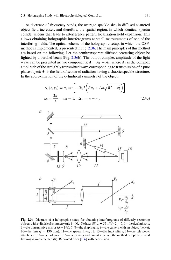
interfering fields. The optical scheme of the holographic setup, in which the OSFmethod is implemented, is presented in Fig. 2.36. The main principles of this method
are based on the following. Let the semitransparent diffused scattering object be
lighted by a parallel beam (Fig. 2.36b). The output complex amplitude of the light
wave can be presented as two components: A = A 1 + A 2 , where A 1 is the complex
amplitude of the straightly transmitted wave corresponding to transmission of a pure
phase object; A 2 is the field of scattered radiation having a chaotic speckle-structure.
In the approximation of the cylindrical symmetry of the object:
A 1 (x 1 y 1 ) = a 0 exp
−ik o 2
Rn c + n
R 2 − x
2
1
,
k 0 =
2π
λ
; a 0 ≡ 1; n = n − n c ,
(2.43)
Fig. 2.36 Diagram of a holographic setup for obtaining interferograms of diffusely scattering
objects with cylindrical symmetry (a): 1—He–Ne laser (W out = 55 mW); 2, 4, 5, 6—the deaf mirrors;
3—the transmissive mirror (R ~ 1%); 7, 8—the diaphragm; 9—the camera with an object (nerve);
10—the lens (f = 130 mm); 11—the spatial filter; 12, 13—the light filters; 14—the telescopic
attachment; 15—the hologram; 16—the camera and circuit in which the method of optical spatial
filtering is implemented (b). Reprinted from [136] with permission
141
At decrease of frequency bands, the average speckle size in diffused scattered
object field increases, and therefore, the spatial region, in which identical spectra
collide, widens that leads to interference pattern localization field expansion. This
allows obtaining holographic interferograms at small measurements of one of the
interfering fields. The optical scheme of the holographic setup, in which the OSFmethod is implemented, is presented in Fig. 2.36. The main principles of this method
are based on the following. Let the semitransparent diffused scattering object be
lighted by a parallel beam (Fig. 2.36b). The output complex amplitude of the light
wave can be presented as two components: A = A 1 + A 2 , where A 1 is the complex
amplitude of the straightly transmitted wave corresponding to transmission of a pure
phase object; A 2 is the field of scattered radiation having a chaotic speckle-structure.
In the approximation of the cylindrical symmetry of the object:
A 1 (x 1 y 1 ) = a 0 exp
−ik o 2
Rn c + n
R 2 − x
2
1
,
k 0 =
2π
λ
; a 0 ≡ 1; n = n − n c ,
(2.43)
Fig. 2.36 Diagram of a holographic setup for obtaining interferograms of diffusely scattering
objects with cylindrical symmetry (a): 1—He–Ne laser (W out = 55 mW); 2, 4, 5, 6—the deaf mirrors;
3—the transmissive mirror (R ~ 1%); 7, 8—the diaphragm; 9—the camera with an object (nerve);
10—the lens (f = 130 mm); 11—the spatial filter; 12, 13—the light filters; 14—the telescopic
attachment; 15—the hologram; 16—the camera and circuit in which the method of optical spatial
filtering is implemented (b). Reprinted from [136] with permission