

2.3 Holographic Study with Electrophysiological Control …
139
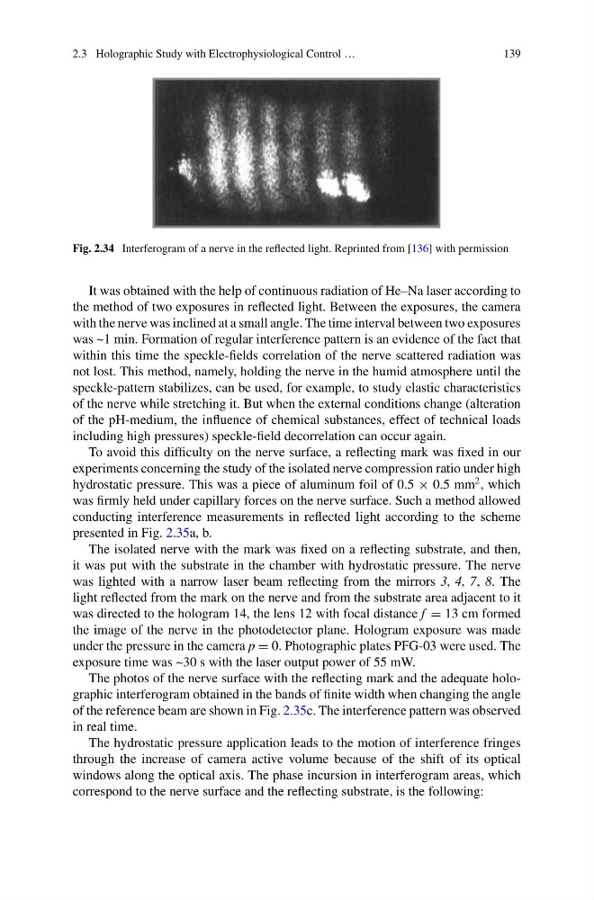
Fig. 2.34 Interferogram of a nerve in the reflected light. Reprinted from [136] with permission
It was obtained with the help of continuous radiation of He–Na laser according to
the method of two exposures in reflected light. Between the exposures, the camera
with the nerve was inclined at a small angle. The time interval between two exposures
was ~1 min. Formation of regular interference pattern is an evidence of the fact that
within this time the speckle-fields correlation of the nerve scattered radiation was
not lost. This method, namely, holding the nerve in the humid atmosphere until the
speckle-pattern stabilizes, can be used, for example, to study elastic characteristics
of the nerve while stretching it. But when the external conditions change (alteration
of the pH-medium, the influence of chemical substances, effect of technical loads
including high pressures) speckle-field decorrelation can occur again.
To avoid this difficulty on the nerve surface, a reflecting mark was fixed in our
experiments concerning the study of the isolated nerve compression ratio under high
hydrostatic pressure. This was a piece of aluminum foil of 0.5 × 0.5 mm
2 , which
was firmly held under capillary forces on the nerve surface. Such a method allowed
conducting interference measurements in reflected light according to the scheme
presented in Fig. 2.35a, b.
The isolated nerve with the mark was fixed on a reflecting substrate, and then,
it was put with the substrate in the chamber with hydrostatic pressure. The nerve
was lighted with a narrow laser beam reflecting from the mirrors 3, 4, 7, 8. The
light reflected from the mark on the nerve and from the substrate area adjacent to it
was directed to the hologram 14, the lens 12 with focal distance f = 13 cm formed
the image of the nerve in the photodetector plane. Hologram exposure was made
under the pressure in the camera p = 0. Photographic plates PFG-03 were used. The
exposure time was ~30 s with the laser output power of 55 mW.
The photos of the nerve surface with the reflecting mark and the adequate holographic interferogram obtained in the bands of finite width when changing the angle
of the reference beam are shown in Fig. 2.35c. The interference pattern was observed
in real time.
The hydrostatic pressure application leads to the motion of interference fringes
through the increase of camera active volume because of the shift of its optical
windows along the optical axis. The phase incursion in interferogram areas, which
correspond to the nerve surface and the reflecting substrate, is the following:
139
Fig. 2.34 Interferogram of a nerve in the reflected light. Reprinted from [136] with permission
It was obtained with the help of continuous radiation of He–Na laser according to
the method of two exposures in reflected light. Between the exposures, the camera
with the nerve was inclined at a small angle. The time interval between two exposures
was ~1 min. Formation of regular interference pattern is an evidence of the fact that
within this time the speckle-fields correlation of the nerve scattered radiation was
not lost. This method, namely, holding the nerve in the humid atmosphere until the
speckle-pattern stabilizes, can be used, for example, to study elastic characteristics
of the nerve while stretching it. But when the external conditions change (alteration
of the pH-medium, the influence of chemical substances, effect of technical loads
including high pressures) speckle-field decorrelation can occur again.
To avoid this difficulty on the nerve surface, a reflecting mark was fixed in our
experiments concerning the study of the isolated nerve compression ratio under high
hydrostatic pressure. This was a piece of aluminum foil of 0.5 × 0.5 mm
2 , which
was firmly held under capillary forces on the nerve surface. Such a method allowed
conducting interference measurements in reflected light according to the scheme
presented in Fig. 2.35a, b.
The isolated nerve with the mark was fixed on a reflecting substrate, and then,
it was put with the substrate in the chamber with hydrostatic pressure. The nerve
was lighted with a narrow laser beam reflecting from the mirrors 3, 4, 7, 8. The
light reflected from the mark on the nerve and from the substrate area adjacent to it
was directed to the hologram 14, the lens 12 with focal distance f = 13 cm formed
the image of the nerve in the photodetector plane. Hologram exposure was made
under the pressure in the camera p = 0. Photographic plates PFG-03 were used. The
exposure time was ~30 s with the laser output power of 55 mW.
The photos of the nerve surface with the reflecting mark and the adequate holographic interferogram obtained in the bands of finite width when changing the angle
of the reference beam are shown in Fig. 2.35c. The interference pattern was observed
in real time.
The hydrostatic pressure application leads to the motion of interference fringes
through the increase of camera active volume because of the shift of its optical
windows along the optical axis. The phase incursion in interferogram areas, which
correspond to the nerve surface and the reflecting substrate, is the following: