

2.2 Holographic Study of Structural and Functional Characteristics …
125
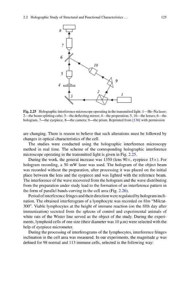
Fig. 2.25 Holographic interference microscope operating in the transmitted light: 1—He–Na laser;
2—the beam splitting cube; 3—the deflecting mirror; 4—the preperation; 5, 10—the lenses; 6—the
hologram, 7—the eyepiece, 8—the camera; 9—the prism. Reprinted from [136] with permission
are changing. There is reason to believe that such alterations must be followed by
changes in optical characteristics of the cell.
The studies were conducted using the holographic interference microscopy
method in real time. The scheme of the corresponding holographic interference
microscope operating in the transmitted light is given in Fig. 2.25.
During the work, the general increase was 1350 (lens 90×, eyepiece 15×). For
hologram recording, a 50 mW laser was used. The hologram of the object beam
was recorded without the preparation, after processing it was placed on the initial
place between the lens and the eyepiece and was lighted with the reference beam.
The interference of the wave recovered from the hologram and the wave distributing
from the preparation under study lead to the formation of an interference pattern in
the form of parallel bands curving in the cell area (Fig. 2.26).
Period of interference fringes and their direction were regulated by hologram inclination. The obtained interferogram of a lymphocyte was recorded on film “Mikrat300”. Viable lymphocytes at the height of immune reaction (on the fifth day after
immunization) secreted from the spleens of control and experimental animals of
white rats of the Wister line served as the object of the study. During the experiments, lymphoid cells of one size (their diameter was 10 μm) were selected with the
help of eyepiece micrometer.
During the processing of interferograms of the lymphocytes, interference fringes
inclination in the cell area was measured. In our experiments, the magnitude ϕ was
defined for 98 normal and 113 immune cells, selected in the following way:
125
Fig. 2.25 Holographic interference microscope operating in the transmitted light: 1—He–Na laser;
2—the beam splitting cube; 3—the deflecting mirror; 4—the preperation; 5, 10—the lenses; 6—the
hologram, 7—the eyepiece, 8—the camera; 9—the prism. Reprinted from [136] with permission
are changing. There is reason to believe that such alterations must be followed by
changes in optical characteristics of the cell.
The studies were conducted using the holographic interference microscopy
method in real time. The scheme of the corresponding holographic interference
microscope operating in the transmitted light is given in Fig. 2.25.
During the work, the general increase was 1350 (lens 90×, eyepiece 15×). For
hologram recording, a 50 mW laser was used. The hologram of the object beam
was recorded without the preparation, after processing it was placed on the initial
place between the lens and the eyepiece and was lighted with the reference beam.
The interference of the wave recovered from the hologram and the wave distributing
from the preparation under study lead to the formation of an interference pattern in
the form of parallel bands curving in the cell area (Fig. 2.26).
Period of interference fringes and their direction were regulated by hologram inclination. The obtained interferogram of a lymphocyte was recorded on film “Mikrat300”. Viable lymphocytes at the height of immune reaction (on the fifth day after
immunization) secreted from the spleens of control and experimental animals of
white rats of the Wister line served as the object of the study. During the experiments, lymphoid cells of one size (their diameter was 10 μm) were selected with the
help of eyepiece micrometer.
During the processing of interferograms of the lymphocytes, interference fringes
inclination in the cell area was measured. In our experiments, the magnitude ϕ was
defined for 98 normal and 113 immune cells, selected in the following way: