

6.2 Hybrid TFET Reconfigurable CAM/SRAM Array Based on a 9T-TFET. . .
75
6.2 Hybrid TFET Reconfigurable CAM/SRAM Array Based
on a 9T-TFET Bitcell
The Reconfigurable 9T-TFET CAM/SRAM (ReCSAM) design is meant for efficient
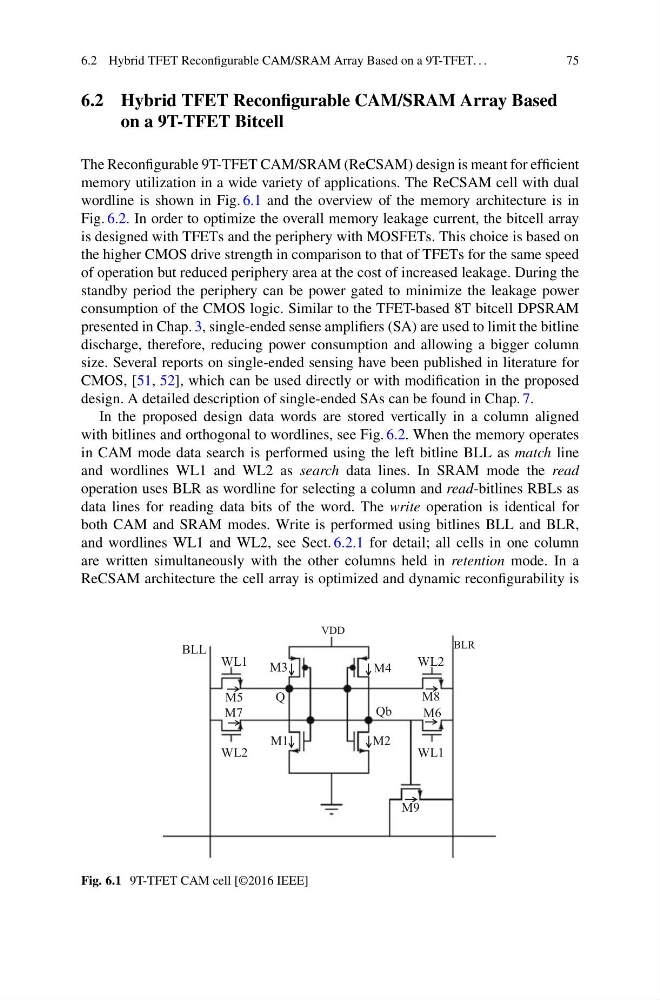
memory utilization in a wide variety of applications. The ReCSAM cell with dual
wordline is shown in Fig. 6.1 and the overview of the memory architecture is in
Fig. 6.2. In order to optimize the overall memory leakage current, the bitcell array
is designed with TFETs and the periphery with MOSFETs. This choice is based on
the higher CMOS drive strength in comparison to that of TFETs for the same speed
of operation but reduced periphery area at the cost of increased leakage. During the
standby period the periphery can be power gated to minimize the leakage power
consumption of the CMOS logic. Similar to the TFET-based 8T bitcell DPSRAM
presented in Chap. 3, single-ended sense amplifiers (SA) are used to limit the bitline
discharge, therefore, reducing power consumption and allowing a bigger column
size. Several reports on single-ended sensing have been published in literature for
CMOS, [51, 52], which can be used directly or with modification in the proposed
design. A detailed description of single-ended SAs can be found in Chap. 7.
In the proposed design data words are stored vertically in a column aligned
with bitlines and orthogonal to wordlines, see Fig. 6.2. When the memory operates
in CAM mode data search is performed using the left bitline BLL as match line
and wordlines WL1 and WL2 as search data lines. In SRAM mode the read
operation uses BLR as wordline for selecting a column and read-bitlines RBLs as
data lines for reading data bits of the word. The write operation is identical for
both CAM and SRAM modes. Write is performed using bitlines BLL and BLR,
and wordlines WL1 and WL2, see Sect. 6.2.1 for detail; all cells in one column
are written simultaneously with the other columns held in retention mode. In a
ReCSAM architecture the cell array is optimized and dynamic reconfigurability is
M9
M3
M1
M2
M4
M5
BLL
WL1
WL2
WL2
WL1
M7
M8
M6
Q
Qb
VDD
BLR
Fig. 6.1 9T-TFET CAM cell [©2016 IEEE]
75
6.2 Hybrid TFET Reconfigurable CAM/SRAM Array Based
on a 9T-TFET Bitcell
The Reconfigurable 9T-TFET CAM/SRAM (ReCSAM) design is meant for efficient
memory utilization in a wide variety of applications. The ReCSAM cell with dual
wordline is shown in Fig. 6.1 and the overview of the memory architecture is in
Fig. 6.2. In order to optimize the overall memory leakage current, the bitcell array
is designed with TFETs and the periphery with MOSFETs. This choice is based on
the higher CMOS drive strength in comparison to that of TFETs for the same speed
of operation but reduced periphery area at the cost of increased leakage. During the
standby period the periphery can be power gated to minimize the leakage power
consumption of the CMOS logic. Similar to the TFET-based 8T bitcell DPSRAM
presented in Chap. 3, single-ended sense amplifiers (SA) are used to limit the bitline
discharge, therefore, reducing power consumption and allowing a bigger column
size. Several reports on single-ended sensing have been published in literature for
CMOS, [51, 52], which can be used directly or with modification in the proposed
design. A detailed description of single-ended SAs can be found in Chap. 7.
In the proposed design data words are stored vertically in a column aligned
with bitlines and orthogonal to wordlines, see Fig. 6.2. When the memory operates
in CAM mode data search is performed using the left bitline BLL as match line
and wordlines WL1 and WL2 as search data lines. In SRAM mode the read
operation uses BLR as wordline for selecting a column and read-bitlines RBLs as
data lines for reading data bits of the word. The write operation is identical for
both CAM and SRAM modes. Write is performed using bitlines BLL and BLR,
and wordlines WL1 and WL2, see Sect. 6.2.1 for detail; all cells in one column
are written simultaneously with the other columns held in retention mode. In a
ReCSAM architecture the cell array is optimized and dynamic reconfigurability is
M9
M3
M1
M2
M4
M5
BLL
WL1
WL2
WL2
WL1
M7
M8
M6
Q
Qb
VDD
BLR
Fig. 6.1 9T-TFET CAM cell [©2016 IEEE]