

5.3 12T-TFET Master-Slave Flip-Flop (MSFF) Design
67
1
10
0,3
0,4
0,5
0,6
TFET-FF
CMOS FF
FinFET FF
FinFET FF-HP
Supply Voltage [V]
T
Setup [ps]
10 0
10 1
10 2
10 3
10 4
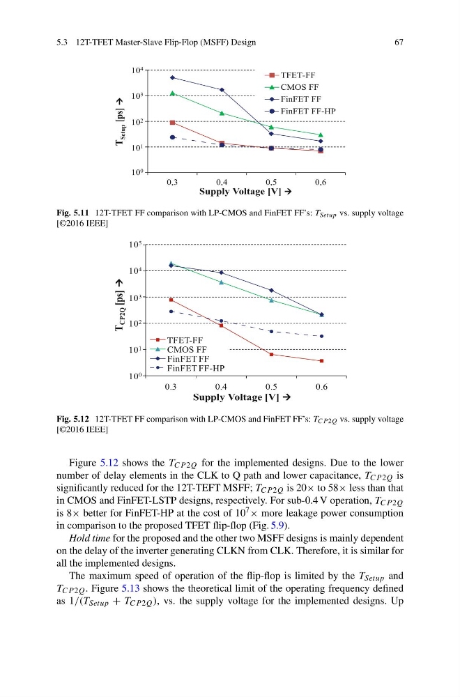
Fig. 5.11 12T-TFET FF comparison with LP-CMOS and FinFET FF’s: T Setup vs. supply voltage
[©2016 IEEE]
1
10
100
0.3
0.4
0.5
0.6
TFET-FF
CMOS FF
FinFET FF
FinFET FF-HP
Supply Voltage [V]
T
CP2Q [ps]
10 0
10 1
10 2
10 3
10 4
10 5
Fig. 5.12 12T-TFET FF comparison with LP-CMOS and FinFET FF’s: T CP 2Q vs. supply voltage
[©2016 IEEE]
Figure 5.12 shows the T CP 2Q for the implemented designs. Due to the lower
number of delay elements in the CLK to Q path and lower capacitance, T CP 2Q is
significantly reduced for the 12T-TEFT MSFF; T CP 2Q is 20× to 58× less than that
in CMOS and FinFET-LSTP designs, respectively. For sub-0.4 V operation, T CP 2Q
is 8× better for FinFET-HP at the cost of 10 7 × more leakage power consumption
in comparison to the proposed TFET flip-flop (Fig. 5.9).
Hold time for the proposed and the other two MSFF designs is mainly dependent
on the delay of the inverter generating CLKN from CLK. Therefore, it is similar for
all the implemented designs.
The maximum speed of operation of the flip-flop is limited by the T Setup and
T CP 2Q . Figure 5.13 shows the theoretical limit of the operating frequency defined
as 1/(T Setup + T CP 2Q ), vs. the supply voltage for the implemented designs. Up
67
1
10
0,3
0,4
0,5
0,6
TFET-FF
CMOS FF
FinFET FF
FinFET FF-HP
Supply Voltage [V]
T
Setup [ps]
10 0
10 1
10 2
10 3
10 4
Fig. 5.11 12T-TFET FF comparison with LP-CMOS and FinFET FF’s: T Setup vs. supply voltage
[©2016 IEEE]
1
10
100
0.3
0.4
0.5
0.6
TFET-FF
CMOS FF
FinFET FF
FinFET FF-HP
Supply Voltage [V]
T
CP2Q [ps]
10 0
10 1
10 2
10 3
10 4
10 5
Fig. 5.12 12T-TFET FF comparison with LP-CMOS and FinFET FF’s: T CP 2Q vs. supply voltage
[©2016 IEEE]
Figure 5.12 shows the T CP 2Q for the implemented designs. Due to the lower
number of delay elements in the CLK to Q path and lower capacitance, T CP 2Q is
significantly reduced for the 12T-TEFT MSFF; T CP 2Q is 20× to 58× less than that
in CMOS and FinFET-LSTP designs, respectively. For sub-0.4 V operation, T CP 2Q
is 8× better for FinFET-HP at the cost of 10 7 × more leakage power consumption
in comparison to the proposed TFET flip-flop (Fig. 5.9).
Hold time for the proposed and the other two MSFF designs is mainly dependent
on the delay of the inverter generating CLKN from CLK. Therefore, it is similar for
all the implemented designs.
The maximum speed of operation of the flip-flop is limited by the T Setup and
T CP 2Q . Figure 5.13 shows the theoretical limit of the operating frequency defined
as 1/(T Setup + T CP 2Q ), vs. the supply voltage for the implemented designs. Up