

108
7 Sensing Techniques
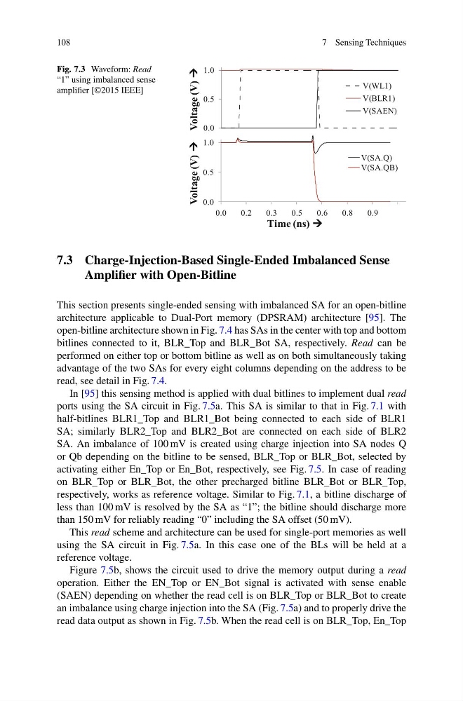
Fig. 7.3 Waveform: Read
“1” using imbalanced sense
amplifier [©2015 IEEE]
Voltage (V)
Time (ns)
Voltage (V)
0.0
0.5
1.0
V(WL1)
V(BLR1)
V(SAEN)
0.0
0.5
1.0
0.0
0.2
0.3
0.5
0.6
0.8
0.9
V(SA.Q)
V(SA.QB)
7.3 Charge-Injection-Based Single-Ended Imbalanced Sense
Amplifier with Open-Bitline
This section presents single-ended sensing with imbalanced SA for an open-bitline
architecture applicable to Dual-Port memory (DPSRAM) architecture [95]. The
open-bitline architecture shown in Fig. 7.4 has SAs in the center with top and bottom
bitlines connected to it, BLR_Top and BLR_Bot SA, respectively. Read can be
performed on either top or bottom bitline as well as on both simultaneously taking
advantage of the two SAs for every eight columns depending on the address to be
read, see detail in Fig. 7.4.
In [95] this sensing method is applied with dual bitlines to implement dual read
ports using the SA circuit in Fig. 7.5a. This SA is similar to that in Fig. 7.1 with
half-bitlines BLR1_Top and BLR1_Bot being connected to each side of BLR1
SA; similarly BLR2_Top and BLR2_Bot are connected on each side of BLR2
SA. An imbalance of 100 mV is created using charge injection into SA nodes Q
or Qb depending on the bitline to be sensed, BLR_Top or BLR_Bot, selected by
activating either En_Top or En_Bot, respectively, see Fig. 7.5. In case of reading
on BLR_Top or BLR_Bot, the other precharged bitline BLR_Bot or BLR_Top,
respectively, works as reference voltage. Similar to Fig. 7.1, a bitline discharge of
less than 100 mV is resolved by the SA as “1”; the bitline should discharge more
than 150 mV for reliably reading “0” including the SA offset (50 mV).
This read scheme and architecture can be used for single-port memories as well
using the SA circuit in Fig. 7.5a. In this case one of the BLs will be held at a
reference voltage.
Figure 7.5b, shows the circuit used to drive the memory output during a read
operation. Either the EN_Top or EN_Bot signal is activated with sense enable
(SAEN) depending on whether the read cell is on BLR_Top or BLR_Bot to create
an imbalance using charge injection into the SA (Fig. 7.5a) and to properly drive the
read data output as shown in Fig. 7.5b. When the read cell is on BLR_Top, En_Top
7 Sensing Techniques
Fig. 7.3 Waveform: Read
“1” using imbalanced sense
amplifier [©2015 IEEE]
Voltage (V)
Time (ns)
Voltage (V)
0.0
0.5
1.0
V(WL1)
V(BLR1)
V(SAEN)
0.0
0.5
1.0
0.0
0.2
0.3
0.5
0.6
0.8
0.9
V(SA.Q)
V(SA.QB)
7.3 Charge-Injection-Based Single-Ended Imbalanced Sense
Amplifier with Open-Bitline
This section presents single-ended sensing with imbalanced SA for an open-bitline
architecture applicable to Dual-Port memory (DPSRAM) architecture [95]. The
open-bitline architecture shown in Fig. 7.4 has SAs in the center with top and bottom
bitlines connected to it, BLR_Top and BLR_Bot SA, respectively. Read can be
performed on either top or bottom bitline as well as on both simultaneously taking
advantage of the two SAs for every eight columns depending on the address to be
read, see detail in Fig. 7.4.
In [95] this sensing method is applied with dual bitlines to implement dual read
ports using the SA circuit in Fig. 7.5a. This SA is similar to that in Fig. 7.1 with
half-bitlines BLR1_Top and BLR1_Bot being connected to each side of BLR1
SA; similarly BLR2_Top and BLR2_Bot are connected on each side of BLR2
SA. An imbalance of 100 mV is created using charge injection into SA nodes Q
or Qb depending on the bitline to be sensed, BLR_Top or BLR_Bot, selected by
activating either En_Top or En_Bot, respectively, see Fig. 7.5. In case of reading
on BLR_Top or BLR_Bot, the other precharged bitline BLR_Bot or BLR_Top,
respectively, works as reference voltage. Similar to Fig. 7.1, a bitline discharge of
less than 100 mV is resolved by the SA as “1”; the bitline should discharge more
than 150 mV for reliably reading “0” including the SA offset (50 mV).
This read scheme and architecture can be used for single-port memories as well
using the SA circuit in Fig. 7.5a. In this case one of the BLs will be held at a
reference voltage.
Figure 7.5b, shows the circuit used to drive the memory output during a read
operation. Either the EN_Top or EN_Bot signal is activated with sense enable
(SAEN) depending on whether the read cell is on BLR_Top or BLR_Bot to create
an imbalance using charge injection into the SA (Fig. 7.5a) and to properly drive the
read data output as shown in Fig. 7.5b. When the read cell is on BLR_Top, En_Top