

96
6 Content-Addressable Memories
Word[0]
Word[2]
Word[N-2]
Word[0]
Memcell
Memcell
Memcell
Memcell
Memcell
Memcell
Memcell
Memcell
Memcell
WTA
WTA
BLR1
BLR2
WTA
WTA
BLR1
BLR2
WTA
WTA
BLR1
BLR2
Winner-Take-All-Logic
SA
SA
SA
SA
SA
SA
d
e
s
a
b
d
r
o
w
h
c
r
a
e
S
e
n
i
l
d
r
o
w
n
o
i
t
c
e
l
e
s
Memcell
Word[1]
Word[N-1]
]
1
[
t
e
S
]
1
[
t
e
S
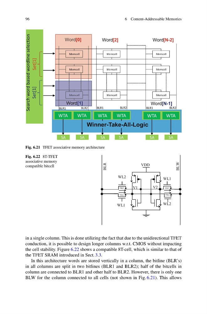
Fig. 6.21 TFET associative memory architecture
Fig. 6.22 8T-TFET
associative memory
compatible bitcell
VDD
BLR
BLW
WL2
WL2
WL1
WL1
V2
V1
TR3
TR4
TR1
TR2
in a single column. This is done utilizing the fact that due to the unidirectional TFET
conduction, it is possible to design longer columns w.r.t. CMOS without impacting
the cell stability. Figure 6.22 shows a compatible 8T-cell, which is similar to that of
the TFET SRAM introduced in Sect. 3.3.
In this architecture words are stored vertically in a column, the bitline (BLR’s)
in all columns are split in two bitlines (BLR1 and BLR2); half of the bitcells in
column are connected to BLR1 and other half to BLR2. However, there is only one
BLW for the column connected to all cells (not shown in Fig. 6.21). This allows
6 Content-Addressable Memories
Word[0]
Word[2]
Word[N-2]
Word[0]
Memcell
Memcell
Memcell
Memcell
Memcell
Memcell
Memcell
Memcell
Memcell
WTA
WTA
BLR1
BLR2
WTA
WTA
BLR1
BLR2
WTA
WTA
BLR1
BLR2
Winner-Take-All-Logic
SA
SA
SA
SA
SA
SA
d
e
s
a
b
d
r
o
w
h
c
r
a
e
S
e
n
i
l
d
r
o
w
n
o
i
t
c
e
l
e
s
Memcell
Word[1]
Word[N-1]
]
1
[
t
e
S
]
1
[
t
e
S
Fig. 6.21 TFET associative memory architecture
Fig. 6.22 8T-TFET
associative memory
compatible bitcell
VDD
BLR
BLW
WL2
WL2
WL1
WL1
V2
V1
TR3
TR4
TR1
TR2
in a single column. This is done utilizing the fact that due to the unidirectional TFET
conduction, it is possible to design longer columns w.r.t. CMOS without impacting
the cell stability. Figure 6.22 shows a compatible 8T-cell, which is similar to that of
the TFET SRAM introduced in Sect. 3.3.
In this architecture words are stored vertically in a column, the bitline (BLR’s)
in all columns are split in two bitlines (BLR1 and BLR2); half of the bitcells in
column are connected to BLR1 and other half to BLR2. However, there is only one
BLW for the column connected to all cells (not shown in Fig. 6.21). This allows