

92
6 Content-Addressable Memories
PRE_WTA
PRE_WTA_N
BL[0]
VDD
GND
VC
WTA
dout_wta[0]
GND
PRE_WTA_N
BL[1]
GND
dout_wta[1]
PRE_WTA
I bias
V[0]
V[1]
I[0]
I[1]
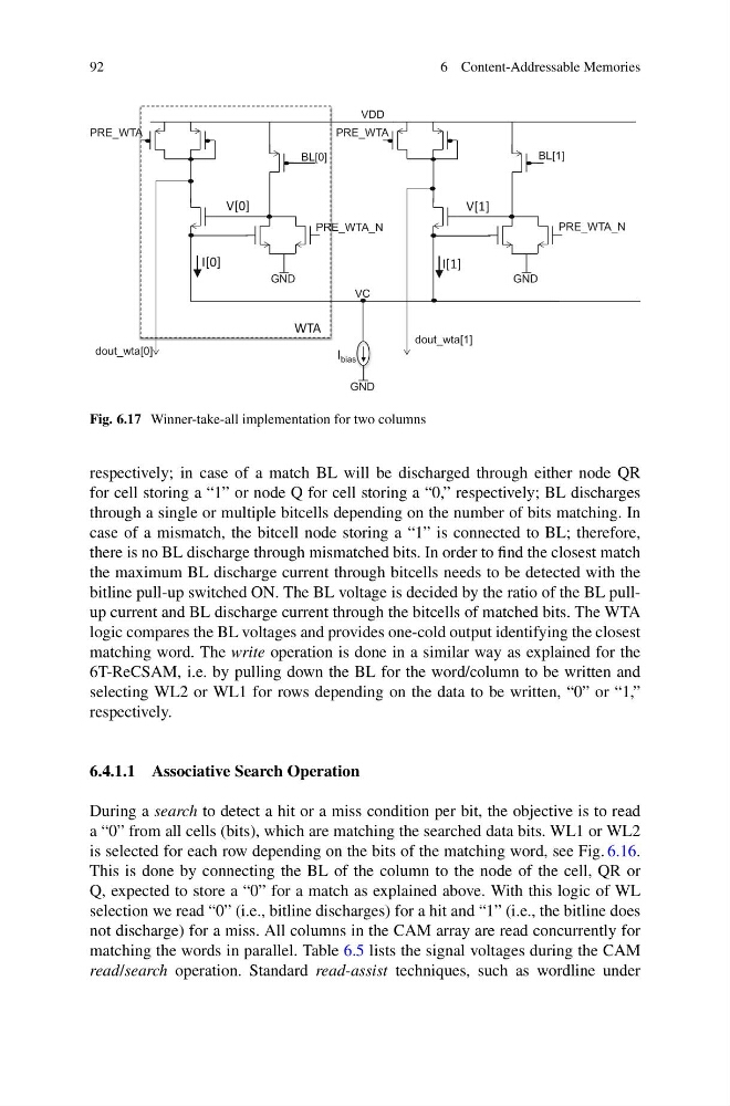
Fig. 6.17 Winner-take-all implementation for two columns
respectively; in case of a match BL will be discharged through either node QR
for cell storing a “1” or node Q for cell storing a “0,” respectively; BL discharges
through a single or multiple bitcells depending on the number of bits matching. In
case of a mismatch, the bitcell node storing a “1” is connected to BL; therefore,
there is no BL discharge through mismatched bits. In order to find the closest match
the maximum BL discharge current through bitcells needs to be detected with the
bitline pull-up switched ON. The BL voltage is decided by the ratio of the BL pullup current and BL discharge current through the bitcells of matched bits. The WTA
logic compares the BL voltages and provides one-cold output identifying the closest
matching word. The write operation is done in a similar way as explained for the
6T-ReCSAM, i.e. by pulling down the BL for the word/column to be written and
selecting WL2 or WL1 for rows depending on the data to be written, “0” or “1,”
respectively.
6.4.1.1 Associative Search Operation
During a search to detect a hit or a miss condition per bit, the objective is to read
a “0” from all cells (bits), which are matching the searched data bits. WL1 or WL2
is selected for each row depending on the bits of the matching word, see Fig. 6.16.
This is done by connecting the BL of the column to the node of the cell, QR or
Q, expected to store a “0” for a match as explained above. With this logic of WL
selection we read “0” (i.e., bitline discharges) for a hit and “1” (i.e., the bitline does
not discharge) for a miss. All columns in the CAM array are read concurrently for
matching the words in parallel. Table 6.5 lists the signal voltages during the CAM
read/search operation. Standard read-assist techniques, such as wordline under
6 Content-Addressable Memories
PRE_WTA
PRE_WTA_N
BL[0]
VDD
GND
VC
WTA
dout_wta[0]
GND
PRE_WTA_N
BL[1]
GND
dout_wta[1]
PRE_WTA
I bias
V[0]
V[1]
I[0]
I[1]
Fig. 6.17 Winner-take-all implementation for two columns
respectively; in case of a match BL will be discharged through either node QR
for cell storing a “1” or node Q for cell storing a “0,” respectively; BL discharges
through a single or multiple bitcells depending on the number of bits matching. In
case of a mismatch, the bitcell node storing a “1” is connected to BL; therefore,
there is no BL discharge through mismatched bits. In order to find the closest match
the maximum BL discharge current through bitcells needs to be detected with the
bitline pull-up switched ON. The BL voltage is decided by the ratio of the BL pullup current and BL discharge current through the bitcells of matched bits. The WTA
logic compares the BL voltages and provides one-cold output identifying the closest
matching word. The write operation is done in a similar way as explained for the
6T-ReCSAM, i.e. by pulling down the BL for the word/column to be written and
selecting WL2 or WL1 for rows depending on the data to be written, “0” or “1,”
respectively.
6.4.1.1 Associative Search Operation
During a search to detect a hit or a miss condition per bit, the objective is to read
a “0” from all cells (bits), which are matching the searched data bits. WL1 or WL2
is selected for each row depending on the bits of the matching word, see Fig. 6.16.
This is done by connecting the BL of the column to the node of the cell, QR or
Q, expected to store a “0” for a match as explained above. With this logic of WL
selection we read “0” (i.e., bitline discharges) for a hit and “1” (i.e., the bitline does
not discharge) for a miss. All columns in the CAM array are read concurrently for
matching the words in parallel. Table 6.5 lists the signal voltages during the CAM
read/search operation. Standard read-assist techniques, such as wordline under