

3.4 Boundary Conditions of the Coupling Model
77
3.4.3 Discontinuous Boundary Conditions for Surface
Tension, Thermal Capillary Force and Recoil Pressure
Next, Eq. (3.35) is simplified to deduce the discontinuous boundary conditions used to
calculate the capturing method of boundary conditions. Several identities on viscous
incompressible fluid are given first before the discontinuous boundary conditions are
deduced.
Since the metal liquid and the metal vapor/plasma in the weld pool are all viscous
fluids, their velocities on the free interface of the keyhole are continuous. Otherwise,
the free interface will be torn or overlapped non-physically. That is, for viscous fluids,
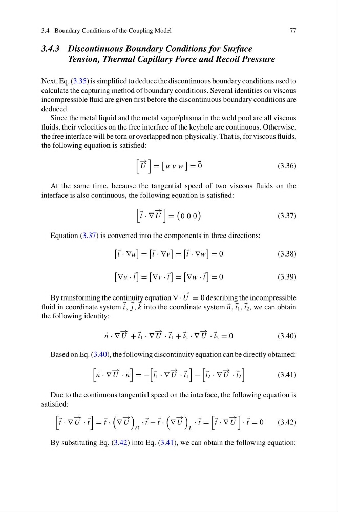
the following equation is satisfied:
− →
U
=
u v w
=
0
(3.36)
At the same time, because the tangential speed of two viscous fluids on the
interface is also continuous, the following equation is satisfied:
t · ∇
− →
U
=
0 0 0
(3.37)
Equation (3.37) is converted into the components in three directions:
t · ∇u
=
t · ∇v
=
t · ∇w
= 0
(3.38)
∇u ·
t
=
∇v ·
t
=
∇w ·
t
= 0
(3.39)
By transforming the continuity equation ∇ ·
− →
U = 0 describing the incompressible
fluid in coordinate system i, j,
k into the coordinate system
n,
t 1 ,
t 2 , we can obtain
the following identity:
n · ∇
− →
U +
t 1 · ∇
− →
U ·
t 1 +
t 2 · ∇
− →
U ·
t 2 = 0
(3.40)
Based on Eq. (3.40), the following discontinuity equation can be directly obtained:
n · ∇
− →
U · ·
n
= −
t 1 · ∇
− →
U ·
t 1
−
t 2 · ∇
− →
U ·
t 2
(3.41)
Due to the continuous tangential speed on the interface, the following equation is
satisfied:
t · ∇
− →
U ·
t
=
t ·
∇
− →
U
G
·
t −
t ·
∇
− →
U
L
·
t =
t · ∇
− →
U
·
t = 0
(3.42)
By substituting Eq. (3.42) into Eq. (3.41), we can obtain the following equation:
77
3.4.3 Discontinuous Boundary Conditions for Surface
Tension, Thermal Capillary Force and Recoil Pressure
Next, Eq. (3.35) is simplified to deduce the discontinuous boundary conditions used to
calculate the capturing method of boundary conditions. Several identities on viscous
incompressible fluid are given first before the discontinuous boundary conditions are
deduced.
Since the metal liquid and the metal vapor/plasma in the weld pool are all viscous
fluids, their velocities on the free interface of the keyhole are continuous. Otherwise,
the free interface will be torn or overlapped non-physically. That is, for viscous fluids,
the following equation is satisfied:
− →
U
=
u v w
=
0
(3.36)
At the same time, because the tangential speed of two viscous fluids on the
interface is also continuous, the following equation is satisfied:
t · ∇
− →
U
=
0 0 0
(3.37)
Equation (3.37) is converted into the components in three directions:
t · ∇u
=
t · ∇v
=
t · ∇w
= 0
(3.38)
∇u ·
t
=
∇v ·
t
=
∇w ·
t
= 0
(3.39)
By transforming the continuity equation ∇ ·
− →
U = 0 describing the incompressible
fluid in coordinate system i, j,
k into the coordinate system
n,
t 1 ,
t 2 , we can obtain
the following identity:
n · ∇
− →
U +
t 1 · ∇
− →
U ·
t 1 +
t 2 · ∇
− →
U ·
t 2 = 0
(3.40)
Based on Eq. (3.40), the following discontinuity equation can be directly obtained:
n · ∇
− →
U · ·
n
= −
t 1 · ∇
− →
U ·
t 1
−
t 2 · ∇
− →
U ·
t 2
(3.41)
Due to the continuous tangential speed on the interface, the following equation is
satisfied:
t · ∇
− →
U ·
t
=
t ·
∇
− →
U
G
·
t −
t ·
∇
− →
U
L
·
t =
t · ∇
− →
U
·
t = 0
(3.42)
By substituting Eq. (3.42) into Eq. (3.41), we can obtain the following equation: