

3.3 Free-Surface Tracking Method
73
− −− →
F B F T = (0, 2d y , F
Z
T − F
Z
B )
(3.22)
where:
d x , d y
Grid step size of x and y equation;
F
Z
L F
Z
R F
Z
B F
Z
T
z coordinate value of the corresponding grid.
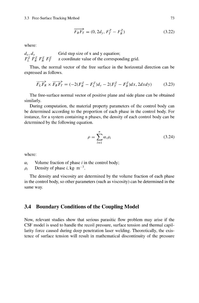
Thus, the normal vector of the free surface in the horizontal direction can be
expressed as follows.
− −− →
F L F R ×
− −− →
F B F T = (−2(F
Z
R − F
Z
L )d y − 2(F
Z
T − F
Z
B )dx, 2dxdy)
(3.23)
The free-surface normal vector of positive plane and side plane can be obtained
similarly.
During computation, the material property parameters of the control body can
be determined according to the proportion of each phase in the control body. For
instance, for a system containing n phases, the density of each control body can be
determined by the following equation.
ρ =
n
l=1
α i ρ i
(3.24)
where:
α i
Volume fraction of phase i in the control body;
ρ i
Density of phase i, kg· m
−3 .
The density and viscosity are determined by the volume fraction of each phase
in the control body, so other parameters (such as viscosity) can be determined in the
same way.
3.4 Boundary Conditions of the Coupling Model
Now, relevant studies show that serious parasitic flow problem may arise if the
CSF model is used to handle the recoil pressure, surface tension and thermal capillarity force caused during deep penetration laser welding. Theoretically, the existence of surface tension will result in mathematical discontinuity of the pressure
73
− −− →
F B F T = (0, 2d y , F
Z
T − F
Z
B )
(3.22)
where:
d x , d y
Grid step size of x and y equation;
F
Z
L F
Z
R F
Z
B F
Z
T
z coordinate value of the corresponding grid.
Thus, the normal vector of the free surface in the horizontal direction can be
expressed as follows.
− −− →
F L F R ×
− −− →
F B F T = (−2(F
Z
R − F
Z
L )d y − 2(F
Z
T − F
Z
B )dx, 2dxdy)
(3.23)
The free-surface normal vector of positive plane and side plane can be obtained
similarly.
During computation, the material property parameters of the control body can
be determined according to the proportion of each phase in the control body. For
instance, for a system containing n phases, the density of each control body can be
determined by the following equation.
ρ =
n
l=1
α i ρ i
(3.24)
where:
α i
Volume fraction of phase i in the control body;
ρ i
Density of phase i, kg· m
−3 .
The density and viscosity are determined by the volume fraction of each phase
in the control body, so other parameters (such as viscosity) can be determined in the
same way.
3.4 Boundary Conditions of the Coupling Model
Now, relevant studies show that serious parasitic flow problem may arise if the
CSF model is used to handle the recoil pressure, surface tension and thermal capillarity force caused during deep penetration laser welding. Theoretically, the existence of surface tension will result in mathematical discontinuity of the pressure