

208
8 Keyhole and Weld Pool Dynamics in Laser Welding with Filler Wires
8.3 Keyhole and Weld Pool Dynamics in Welding
with Filler Wires
8.3.1 Behaviors of Transient Keyholes and Weld Pools Under
Free Transition Conditions
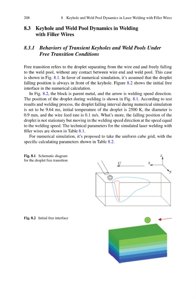
Free transition refers to the droplet separating from the wire end and freely falling
to the weld pool, without any contact between wire end and weld pool. This case
is shown in Fig. 8.1. In favor of numerical simulation, it’s assumed that the droplet
falling position is always in front of the keyhole. Figure 8.2 shows the initial free
interface in the numerical calculation.
In Fig. 8.2, the block is parent metal, and the arrow is welding speed direction.
The position of the droplet during welding is shown in Fig. 8.1. According to test
results and welding process, the droplet falling interval during numerical simulation
is set to be 9.64 ms, initial temperature of the droplet is 2500 K, the diameter is
0.9 mm, and the wire feed rate is 0.1 m/s. What’s more, the falling position of the
droplet is not stationary but moving in the welding speed direction at the speed equal
to the welding speed. The technical parameters for the simulated laser welding with
filler wires are shown in Table 8.1.
For numerical simulation, it’s proposed to take the uniform cube grid, with the
specific calculating parameters shown in Table 8.2.
Fig. 8.1 Schematic diagram
for the droplet free transition
Fig. 8.2 Initial free interface
8 Keyhole and Weld Pool Dynamics in Laser Welding with Filler Wires
8.3 Keyhole and Weld Pool Dynamics in Welding
with Filler Wires
8.3.1 Behaviors of Transient Keyholes and Weld Pools Under
Free Transition Conditions
Free transition refers to the droplet separating from the wire end and freely falling
to the weld pool, without any contact between wire end and weld pool. This case
is shown in Fig. 8.1. In favor of numerical simulation, it’s assumed that the droplet
falling position is always in front of the keyhole. Figure 8.2 shows the initial free
interface in the numerical calculation.
In Fig. 8.2, the block is parent metal, and the arrow is welding speed direction.
The position of the droplet during welding is shown in Fig. 8.1. According to test
results and welding process, the droplet falling interval during numerical simulation
is set to be 9.64 ms, initial temperature of the droplet is 2500 K, the diameter is
0.9 mm, and the wire feed rate is 0.1 m/s. What’s more, the falling position of the
droplet is not stationary but moving in the welding speed direction at the speed equal
to the welding speed. The technical parameters for the simulated laser welding with
filler wires are shown in Table 8.1.
For numerical simulation, it’s proposed to take the uniform cube grid, with the
specific calculating parameters shown in Table 8.2.
Fig. 8.1 Schematic diagram
for the droplet free transition
Fig. 8.2 Initial free interface