

8.3 Keyhole and Weld Pool Dynamics in Welding with Filler Wires
209
Table 8.1 Technical parameters of laser welding with filler wires
Laser power/kw Laser spot radius/mm Defocusing amount/mm Welding speed/ (m/min)
1.5
0.2
0.0
3
Table 8.2 Numerical simulation parameters
Grid quantity
Spatial step/m
Time step/s
Initial temperature of
parent metal/K
Ambient
temperature/K
160 × 60 × 100
3.0 × 10 –5
3.0 × 10 –6
300
300
The welding parent metal is TC4, and the physical property parameters are shown
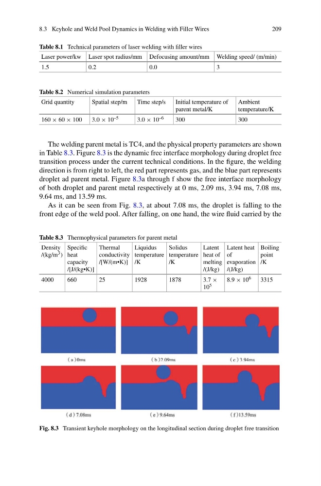
in Table 8.3. Figure 8.3 is the dynamic free interface morphology during droplet free
transition process under the current technical conditions. In the figure, the welding
direction is from right to left, the red part represents gas, and the blue part represents
droplet ad parent metal. Figure 8.3a through f show the free interface morphology
of both droplet and parent metal respectively at 0 ms, 2.09 ms, 3.94 ms, 7.08 ms,
9.64 ms, and 13.59 ms.
As it can be seen from Fig. 8.3, at about 7.08 ms, the droplet is falling to the
front edge of the weld pool. After falling, on one hand, the wire fluid carried by the
Table 8.3 Thermophysical parameters for parent metal
Density
/(kg/m 3 )
Specific
heat
capacity
/[J/(kg•K)]
Thermal
conductivity
/[W/(m•K)]
Liquidus
temperature
/K
Solidus
temperature
/K
Latent
heat of
melting
/(J/kg)
Latent heat
of
evaporation
/(J/kg)
Boiling
point
/K
4000
660
25
1928
1878
3.7 ×
10 5
8.9 × 10 6
3315
Fig. 8.3 Transient keyhole morphology on the longitudinal section during droplet free transition
209
Table 8.1 Technical parameters of laser welding with filler wires
Laser power/kw Laser spot radius/mm Defocusing amount/mm Welding speed/ (m/min)
1.5
0.2
0.0
3
Table 8.2 Numerical simulation parameters
Grid quantity
Spatial step/m
Time step/s
Initial temperature of
parent metal/K
Ambient
temperature/K
160 × 60 × 100
3.0 × 10 –5
3.0 × 10 –6
300
300
The welding parent metal is TC4, and the physical property parameters are shown
in Table 8.3. Figure 8.3 is the dynamic free interface morphology during droplet free
transition process under the current technical conditions. In the figure, the welding
direction is from right to left, the red part represents gas, and the blue part represents
droplet ad parent metal. Figure 8.3a through f show the free interface morphology
of both droplet and parent metal respectively at 0 ms, 2.09 ms, 3.94 ms, 7.08 ms,
9.64 ms, and 13.59 ms.
As it can be seen from Fig. 8.3, at about 7.08 ms, the droplet is falling to the
front edge of the weld pool. After falling, on one hand, the wire fluid carried by the
Table 8.3 Thermophysical parameters for parent metal
Density
/(kg/m 3 )
Specific
heat
capacity
/[J/(kg•K)]
Thermal
conductivity
/[W/(m•K)]
Liquidus
temperature
/K
Solidus
temperature
/K
Latent
heat of
melting
/(J/kg)
Latent heat
of
evaporation
/(J/kg)
Boiling
point
/K
4000
660
25
1928
1878
3.7 ×
10 5
8.9 × 10 6
3315
Fig. 8.3 Transient keyhole morphology on the longitudinal section during droplet free transition