

206
8 Keyhole and Weld Pool Dynamics in Laser Welding with Filler Wires
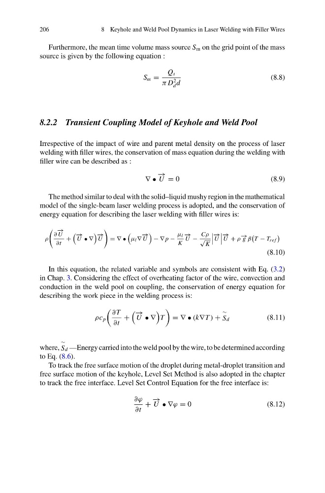
Furthermore, the mean time volume mass source S m on the grid point of the mass
source is given by the following equation :
S m =
Q t
π D
2
d d
(8.8)
8.2.2 Transient Coupling Model of Keyhole and Weld Pool
Irrespective of the impact of wire and parent metal density on the process of laser
welding with filler wires, the conservation of mass equation during the welding with
filler wire can be described as :
∇ •
− →
U = 0
(8.9)
The method similar to deal with the solid–liquid mushy region in the mathematical
model of the single-beam laser welding process is adopted, and the conservation of
energy equation for describing the laser welding with filler wires is:
ρ
∂
− →
U
∂t
+
− →
U • ∇
− →
U
= ∇ •
μ l ∇
− →
U
− ∇ p −
μ l
K
− →
U −
Cρ
√
K
− →
U
− →
U + ρ − → g β
T − T re f
(8.10)
In this equation, the related variable and symbols are consistent with Eq. (3.2)
in Chap. 3. Considering the effect of overheating factor of the wire, convection and
conduction in the weld pool on coupling, the conservation of energy equation for
describing the work piece in the welding process is:
ρc p
∂ T
∂t
+
− →
U • ∇
T
= ∇ • (k∇T ) +
∼
Sd
(8.11)
where,
∼
Sd —Energy carried into the weld pool by the wire, to be determined according
to Eq. (8.6).
To track the free surface motion of the droplet during metal-droplet transition and
free surface motion of the keyhole, Level Set Method is also adopted in the chapter
to track the free interface. Level Set Control Equation for the free interface is:
∂ϕ
∂t
+
− →
U • ∇ϕ = 0
(8.12)
8 Keyhole and Weld Pool Dynamics in Laser Welding with Filler Wires
Furthermore, the mean time volume mass source S m on the grid point of the mass
source is given by the following equation :
S m =
Q t
π D
2
d d
(8.8)
8.2.2 Transient Coupling Model of Keyhole and Weld Pool
Irrespective of the impact of wire and parent metal density on the process of laser
welding with filler wires, the conservation of mass equation during the welding with
filler wire can be described as :
∇ •
− →
U = 0
(8.9)
The method similar to deal with the solid–liquid mushy region in the mathematical
model of the single-beam laser welding process is adopted, and the conservation of
energy equation for describing the laser welding with filler wires is:
ρ
∂
− →
U
∂t
+
− →
U • ∇
− →
U
= ∇ •
μ l ∇
− →
U
− ∇ p −
μ l
K
− →
U −
Cρ
√
K
− →
U
− →
U + ρ − → g β
T − T re f
(8.10)
In this equation, the related variable and symbols are consistent with Eq. (3.2)
in Chap. 3. Considering the effect of overheating factor of the wire, convection and
conduction in the weld pool on coupling, the conservation of energy equation for
describing the work piece in the welding process is:
ρc p
∂ T
∂t
+
− →
U • ∇
T
= ∇ • (k∇T ) +
∼
Sd
(8.11)
where,
∼
Sd —Energy carried into the weld pool by the wire, to be determined according
to Eq. (8.6).
To track the free surface motion of the droplet during metal-droplet transition and
free surface motion of the keyhole, Level Set Method is also adopted in the chapter
to track the free interface. Level Set Control Equation for the free interface is:
∂ϕ
∂t
+
− →
U • ∇ϕ = 0
(8.12)