

144
5 Dynamic Behaviors of Metal Vapor/Plasma Plume …
− →
Q =
⎡
⎢
⎢
⎢
⎢
⎢
⎣
ρ
ρu
ρv
ρw
E
⎤
⎥
⎥
⎥
⎥
⎥
⎦
,
− →
F =
⎡
⎢
⎢
⎢
⎢
⎢
⎣
ρu
ρu
2
+ p
ρuv
ρuw
u(E + p)
⎤
⎥
⎥
⎥
⎥
⎥
⎦
,
− →
G =
⎡
⎢
⎢
⎢
⎢
⎢
⎣
ρv
ρuv
ρv
2
+ p
ρvw
u(E + p)
⎤
⎥
⎥
⎥
⎥
⎥
⎦
,
− →
H =
⎡
⎢
⎢
⎢
⎢
⎢
⎣
ρw
ρwu
ρwv
ρw
2
+ p
u(E + p)
⎤
⎥
⎥
⎥
⎥
⎥
⎦
,
− →
S =
⎡
⎢
⎢
⎢
⎢
⎢
⎣
0
0
0
0
∇(k g ∇T ) + ηI R
⎤
⎥
⎥
⎥
⎥
⎥
⎦
;
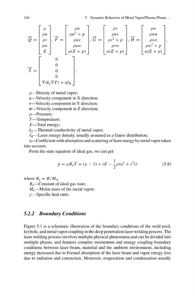
ρ—Density of metal vapor;
u—Velocity component in X direction;
v—Velocity component in Y direction;
w—Velocity component in Z direction;
p—Pressure;
T —Temperature;
E—Total energy;
k g —Thermal conductivity of metal vapor;
I R —Laser energy density, usually assumed as a Gauss distribution;
η—Coefficient with absorption and scattering of laser energy by metal vapor taken
into account.
From the state equation of ideal gas, we can get:
p = ρ R a T = (γ − 1) × (E −
1
2
ρ(u
2
+ v
2
))
(5.8)
where R a = R/M a ;
R a —Constant of ideal gas state;
M a —Molar mass of the metal vapor;
γ —Specific heat ratio.
5.2.2 Boundary Conditions
Figure 5.1 is a schematic illustration of the boundary conditions of the weld pool,
keyhole, and metal vapor coupling in the deep penetration laser welding process. The
laser welding process involves multiple physical phenomena and can be divided into
multiple phases, and features complex momentum and energy coupling boundary
conditions between laser beam, material and the ambient environment, including
energy increased due to Fresnel absorption of the laser beam and vapor energy loss
due to radiation and convection. Moreover, evaporation and condensation usually
5 Dynamic Behaviors of Metal Vapor/Plasma Plume …
− →
Q =
⎡
⎢
⎢
⎢
⎢
⎢
⎣
ρ
ρu
ρv
ρw
E
⎤
⎥
⎥
⎥
⎥
⎥
⎦
,
− →
F =
⎡
⎢
⎢
⎢
⎢
⎢
⎣
ρu
ρu
2
+ p
ρuv
ρuw
u(E + p)
⎤
⎥
⎥
⎥
⎥
⎥
⎦
,
− →
G =
⎡
⎢
⎢
⎢
⎢
⎢
⎣
ρv
ρuv
ρv
2
+ p
ρvw
u(E + p)
⎤
⎥
⎥
⎥
⎥
⎥
⎦
,
− →
H =
⎡
⎢
⎢
⎢
⎢
⎢
⎣
ρw
ρwu
ρwv
ρw
2
+ p
u(E + p)
⎤
⎥
⎥
⎥
⎥
⎥
⎦
,
− →
S =
⎡
⎢
⎢
⎢
⎢
⎢
⎣
0
0
0
0
∇(k g ∇T ) + ηI R
⎤
⎥
⎥
⎥
⎥
⎥
⎦
;
ρ—Density of metal vapor;
u—Velocity component in X direction;
v—Velocity component in Y direction;
w—Velocity component in Z direction;
p—Pressure;
T —Temperature;
E—Total energy;
k g —Thermal conductivity of metal vapor;
I R —Laser energy density, usually assumed as a Gauss distribution;
η—Coefficient with absorption and scattering of laser energy by metal vapor taken
into account.
From the state equation of ideal gas, we can get:
p = ρ R a T = (γ − 1) × (E −
1
2
ρ(u
2
+ v
2
))
(5.8)
where R a = R/M a ;
R a —Constant of ideal gas state;
M a —Molar mass of the metal vapor;
γ —Specific heat ratio.
5.2.2 Boundary Conditions
Figure 5.1 is a schematic illustration of the boundary conditions of the weld pool,
keyhole, and metal vapor coupling in the deep penetration laser welding process. The
laser welding process involves multiple physical phenomena and can be divided into
multiple phases, and features complex momentum and energy coupling boundary
conditions between laser beam, material and the ambient environment, including
energy increased due to Fresnel absorption of the laser beam and vapor energy loss
due to radiation and convection. Moreover, evaporation and condensation usually