

84
3 Modeling Composite Structures
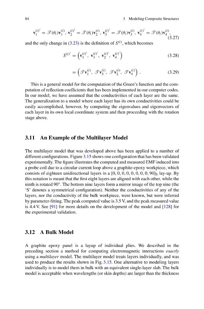
v
(i)
1 = T (θ i )v
(i)
1 , v
(i)
2 = T (θ i )v
(i)
2 , v
(i)
3 = T (θ i )v
(i)
3 , v
(i)
4 = T (θ i )v
(i)
4 ,
(3.27)
and the only change in (3.23) is the definition of S (i) , which becomes
S
(i) =
v
(i)
1 , v
(i)
3 , v
(i)
2 , v
(i)
4
(3.28)
=
T v
(i)
1 , T v
(i)
3 , T v
(i)
2 , T v
(i)
4
.
(3.29)
This is a general model for the computation of the Green’s function and the computation of reflection coefficients that has been implemented in our computer codes.
In our model, we have assumed that the conductivities of each layer are the same.
The generalization to a model where each layer has its own conductivities could be
easily accomplished, however, by computing the eigenvalues and eigenvectors of
each layer in its own local coordinate system and then proceeding with the rotation
stage above.
3.11 An Example of the Multilayer Model
The multilayer model that was developed above has been applied to a number of
different configurations. Figure 3.15 shows one configuration that has been validated
experimentally. The figure illustrates the computed and measured EMF induced into
a probe coil due to a circular current loop above a graphite-epoxy workpiece, which
consists of eighteen unidirectional layers in a [0, 0, 0, 0, 0, 0, 0, 0, 90] S lay-up. By
this notation is meant that the first eight layers are aligned with each other, while the
ninth is rotated 90 ◦ . The bottom nine layers form a mirror image of the top nine (the
‘S’ denotes a symmetrical configuration). Neither the conductivities of any of the
layers, nor the conductivity of the bulk workpiece, were known, but were inferred
by parameter-fitting. The peak computed value is 3.5 V, and the peak measured value
is 4.4 V. See [91] for more details on the development of the model and [128] for
the experimental validation.
3.12 A Bulk Model
A graphite epoxy panel is a layup of individual plies. We described in the
preceding section a method for computing electromagnetic interactions exactly
using a multilayer model. The multilayer model treats layers individually, and was
used to produce the results shown in Fig. 3.15. One alternative to modeling layers
individually is to model them in bulk with an equivalent single-layer slab. The bulk
model is acceptable when wavelengths (or skin depths) are larger than the thickness
3 Modeling Composite Structures
v
(i)
1 = T (θ i )v
(i)
1 , v
(i)
2 = T (θ i )v
(i)
2 , v
(i)
3 = T (θ i )v
(i)
3 , v
(i)
4 = T (θ i )v
(i)
4 ,
(3.27)
and the only change in (3.23) is the definition of S (i) , which becomes
S
(i) =
v
(i)
1 , v
(i)
3 , v
(i)
2 , v
(i)
4
(3.28)
=
T v
(i)
1 , T v
(i)
3 , T v
(i)
2 , T v
(i)
4
.
(3.29)
This is a general model for the computation of the Green’s function and the computation of reflection coefficients that has been implemented in our computer codes.
In our model, we have assumed that the conductivities of each layer are the same.
The generalization to a model where each layer has its own conductivities could be
easily accomplished, however, by computing the eigenvalues and eigenvectors of
each layer in its own local coordinate system and then proceeding with the rotation
stage above.
3.11 An Example of the Multilayer Model
The multilayer model that was developed above has been applied to a number of
different configurations. Figure 3.15 shows one configuration that has been validated
experimentally. The figure illustrates the computed and measured EMF induced into
a probe coil due to a circular current loop above a graphite-epoxy workpiece, which
consists of eighteen unidirectional layers in a [0, 0, 0, 0, 0, 0, 0, 0, 90] S lay-up. By
this notation is meant that the first eight layers are aligned with each other, while the
ninth is rotated 90 ◦ . The bottom nine layers form a mirror image of the top nine (the
‘S’ denotes a symmetrical configuration). Neither the conductivities of any of the
layers, nor the conductivity of the bulk workpiece, were known, but were inferred
by parameter-fitting. The peak computed value is 3.5 V, and the peak measured value
is 4.4 V. See [91] for more details on the development of the model and [128] for
the experimental validation.
3.12 A Bulk Model
A graphite epoxy panel is a layup of individual plies. We described in the
preceding section a method for computing electromagnetic interactions exactly
using a multilayer model. The multilayer model treats layers individually, and was
used to produce the results shown in Fig. 3.15. One alternative to modeling layers
individually is to model them in bulk with an equivalent single-layer slab. The bulk
model is acceptable when wavelengths (or skin depths) are larger than the thickness