

10.8 Measuring the Frequency Response of Saline
269
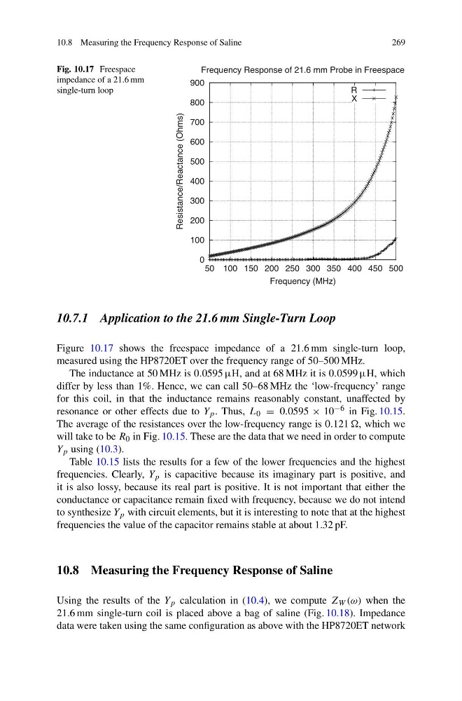
Fig. 10.17 Freespace
impedance of a 21.6 mm
single-turn loop
0
100
200
300
400
500
600
700
800
900
50 100 150 200 250 300 350 400 450 500
Resistance/Reactance (Ohms)
Frequency (MHz)
Frequency Response of 21.6 mm Probe in Freespace
R
X
10.7.1 Application to the 21.6 mm Single-Turn Loop
Figure 10.17 shows the freespace impedance of a 21.6 mm single-turn loop,
measured using the HP8720ET over the frequency range of 50–500 MHz.
The inductance at 50 MHz is 0.0595 µH, and at 68 MHz it is 0.0599 µH, which
differ by less than 1%. Hence, we can call 50–68 MHz the ‘low-frequency’ range
for this coil, in that the inductance remains reasonably constant, unaffected by
resonance or other effects due to Y p . Thus, L 0 = 0.0595 × 10 −6 in Fig. 10.15.
The average of the resistances over the low-frequency range is 0.121 , which we
will take to be R 0 in Fig. 10.15. These are the data that we need in order to compute
Y p using (10.3).
Table 10.15 lists the results for a few of the lower frequencies and the highest
frequencies. Clearly, Y p is capacitive because its imaginary part is positive, and
it is also lossy, because its real part is positive. It is not important that either the
conductance or capacitance remain fixed with frequency, because we do not intend
to synthesize Y p with circuit elements, but it is interesting to note that at the highest
frequencies the value of the capacitor remains stable at about 1.32 pF.
10.8 Measuring the Frequency Response of Saline
Using the results of the Y p calculation in (10.4), we compute Z W (ω) when the
21.6 mm single-turn coil is placed above a bag of saline (Fig. 10.18). Impedance
data were taken using the same configuration as above with the HP8720ET network
269
Fig. 10.17 Freespace
impedance of a 21.6 mm
single-turn loop
0
100
200
300
400
500
600
700
800
900
50 100 150 200 250 300 350 400 450 500
Resistance/Reactance (Ohms)
Frequency (MHz)
Frequency Response of 21.6 mm Probe in Freespace
R
X
10.7.1 Application to the 21.6 mm Single-Turn Loop
Figure 10.17 shows the freespace impedance of a 21.6 mm single-turn loop,
measured using the HP8720ET over the frequency range of 50–500 MHz.
The inductance at 50 MHz is 0.0595 µH, and at 68 MHz it is 0.0599 µH, which
differ by less than 1%. Hence, we can call 50–68 MHz the ‘low-frequency’ range
for this coil, in that the inductance remains reasonably constant, unaffected by
resonance or other effects due to Y p . Thus, L 0 = 0.0595 × 10 −6 in Fig. 10.15.
The average of the resistances over the low-frequency range is 0.121 , which we
will take to be R 0 in Fig. 10.15. These are the data that we need in order to compute
Y p using (10.3).
Table 10.15 lists the results for a few of the lower frequencies and the highest
frequencies. Clearly, Y p is capacitive because its imaginary part is positive, and
it is also lossy, because its real part is positive. It is not important that either the
conductance or capacitance remain fixed with frequency, because we do not intend
to synthesize Y p with circuit elements, but it is interesting to note that at the highest
frequencies the value of the capacitor remains stable at about 1.32 pF.
10.8 Measuring the Frequency Response of Saline
Using the results of the Y p calculation in (10.4), we compute Z W (ω) when the
21.6 mm single-turn coil is placed above a bag of saline (Fig. 10.18). Impedance
data were taken using the same configuration as above with the HP8720ET network