

4.4 Rapid Modulation of Circular Polarisation States for Circular …
83
r s =
n r cos(θ i ) − i
n 2
r sin
2
(θ i ) − 1
n r cos(θ i ) + i
n 2
r sin
2
(θ i ) − 1
,
(4.12)
r p =
cos(θ i ) − in r
n 2
r sin
2
(θ i ) − 1
cos(θ i ) + in r
n 2
r sin
2
(θ i ) − 1
.
(4.13)
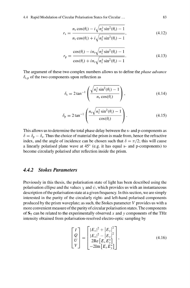
The argument of these two complex numbers allows us to define the phase advance
δ s,p of the two components upon reflection as
δ s = 2 tan
−1
⎛
⎝
n 2
r sin
2
(θ i ) − 1
n r cos(θ i )
⎞
⎠ ,
(4.14)
δ p = 2 tan
−1
⎛
⎝
n r
n 2
r sin
2
(θ i ) − 1
cos(θ i )
⎞
⎠ .
(4.15)
This allows us to determine the total phase delay between the s- and p-components as
δ = δ p − δ s . Thus the choice of material the prism is made from, hence the refractive
index, and the angle of incidence can be chosen such that δ = π/2; this will cause
a linearly polarised plane wave at 45
◦ (e.g. it has equal s- and p-components) to
become circularly polarised after reflection inside the prism.
4.4.2 Stokes Parameters
Previously in this thesis, the polarisation state of light has been described using the
polarisation ellipse and the values χ and ψ, which provides us with an instantaneous
description of the polarisation state at a given frequency. In this section, we are simply
interested in the purity of the circularly right- and left-hand polarised components
produced by the prism waveplate; as such, the Stokes parameter V provides us with a
more convenient measure of the purity of circular polarisation states. The components
of S T can be related to the experimentally observed x and y components of the THz
intensity obtained from polarisation-resolved electro-optic sampling by
⎡
⎢
⎢
⎣
I
Q
U
V
⎤
⎥
⎥
⎦ =
⎡
⎢
⎢
⎢
⎣
|E x |
2
+
E y
2
|E x |
2
−
E y
2
2Re
E x E
∗
y
−2Im
E x E
∗
y
⎤
⎥
⎥
⎥
⎦
,
(4.16)
83
r s =
n r cos(θ i ) − i
n 2
r sin
2
(θ i ) − 1
n r cos(θ i ) + i
n 2
r sin
2
(θ i ) − 1
,
(4.12)
r p =
cos(θ i ) − in r
n 2
r sin
2
(θ i ) − 1
cos(θ i ) + in r
n 2
r sin
2
(θ i ) − 1
.
(4.13)
The argument of these two complex numbers allows us to define the phase advance
δ s,p of the two components upon reflection as
δ s = 2 tan
−1
⎛
⎝
n 2
r sin
2
(θ i ) − 1
n r cos(θ i )
⎞
⎠ ,
(4.14)
δ p = 2 tan
−1
⎛
⎝
n r
n 2
r sin
2
(θ i ) − 1
cos(θ i )
⎞
⎠ .
(4.15)
This allows us to determine the total phase delay between the s- and p-components as
δ = δ p − δ s . Thus the choice of material the prism is made from, hence the refractive
index, and the angle of incidence can be chosen such that δ = π/2; this will cause
a linearly polarised plane wave at 45
◦ (e.g. it has equal s- and p-components) to
become circularly polarised after reflection inside the prism.
4.4.2 Stokes Parameters
Previously in this thesis, the polarisation state of light has been described using the
polarisation ellipse and the values χ and ψ, which provides us with an instantaneous
description of the polarisation state at a given frequency. In this section, we are simply
interested in the purity of the circularly right- and left-hand polarised components
produced by the prism waveplate; as such, the Stokes parameter V provides us with a
more convenient measure of the purity of circular polarisation states. The components
of S T can be related to the experimentally observed x and y components of the THz
intensity obtained from polarisation-resolved electro-optic sampling by
⎡
⎢
⎢
⎣
I
Q
U
V
⎤
⎥
⎥
⎦ =
⎡
⎢
⎢
⎢
⎣
|E x |
2
+
E y
2
|E x |
2
−
E y
2
2Re
E x E
∗
y
−2Im
E x E
∗
y
⎤
⎥
⎥
⎥
⎦
,
(4.16)