

82
4 Scalable Interdigitated Photoconductive Emitters for the Electrical …
4.4 Rapid Modulation of Circular Polarisation States for
Circular Dichroic Spectroscopy
Following from the method used to convert linear THz polarisation states into circular THz polarisation states by Hirota et al. in reference [8], this section will outline
a similar setup making use of the multi-pixel PCEs reported earlier in this chapter.
As will be shown, the advantage of the multi-pixel PCE in such a setup is the ability to arbitrarily change the polarisation angle of the linear THz pulse, allowing
optimisation of the circular THz polarisation state.
4.4.1 Converting from Linear to Circular Polarisation via a
Prism
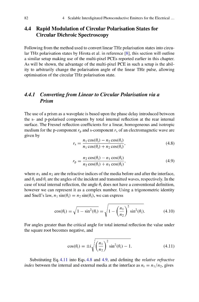
The use of a prism as a waveplate is based upon the phase delay introduced between
the s- and p-polarised components by total internal reflection at the rear internal
surface. The Fresnel reflection coefficients for a linear, homogeneous and isotropic
medium for the p-component r p and s-component r s of an electromagnetic wave are
given by
r s =
n 1 cos(θ i ) − n 2 cos(θ t )
n 1 cos(θ i ) + n 2 cos(θ t )
,
(4.8)
r p =
n 2 cos(θ i ) − n 1 cos(θ t )
n 2 cos(θ i ) + n 1 cos(θ t )
,
(4.9)
where n 1 and n 2 are the refractive indices of the media before and after the interface,
and θ i and θ t are the angles of the incident and transmitted waves, respectively. In the
case of total internal reflection, the angle θ t does not have a conventional definition,
however we can represent it as a complex number. Using a trigonometric identity
and Snell’s law, n 1 sin(θ i ) = n 2 sin(θ t ), we can express
cos(θ t ) =
1 − sin
2
(θ t ) =
1 −
n 1
n 2
2
sin
2
(θ i ).
(4.10)
For angles greater than the critical angle for total internal reflection the value under
the square root becomes negative, and
cos(θ t ) = ±i
n 1
n 2
2
sin
2
(θ i ) − 1.
(4.11)
Substituting Eq. 4.11 into Eqs. 4.8 and 4.9, and defining the relative refractive
index between the internal and external media at the interface as n r = n 1 /n 2 , gives
4 Scalable Interdigitated Photoconductive Emitters for the Electrical …
4.4 Rapid Modulation of Circular Polarisation States for
Circular Dichroic Spectroscopy
Following from the method used to convert linear THz polarisation states into circular THz polarisation states by Hirota et al. in reference [8], this section will outline
a similar setup making use of the multi-pixel PCEs reported earlier in this chapter.
As will be shown, the advantage of the multi-pixel PCE in such a setup is the ability to arbitrarily change the polarisation angle of the linear THz pulse, allowing
optimisation of the circular THz polarisation state.
4.4.1 Converting from Linear to Circular Polarisation via a
Prism
The use of a prism as a waveplate is based upon the phase delay introduced between
the s- and p-polarised components by total internal reflection at the rear internal
surface. The Fresnel reflection coefficients for a linear, homogeneous and isotropic
medium for the p-component r p and s-component r s of an electromagnetic wave are
given by
r s =
n 1 cos(θ i ) − n 2 cos(θ t )
n 1 cos(θ i ) + n 2 cos(θ t )
,
(4.8)
r p =
n 2 cos(θ i ) − n 1 cos(θ t )
n 2 cos(θ i ) + n 1 cos(θ t )
,
(4.9)
where n 1 and n 2 are the refractive indices of the media before and after the interface,
and θ i and θ t are the angles of the incident and transmitted waves, respectively. In the
case of total internal reflection, the angle θ t does not have a conventional definition,
however we can represent it as a complex number. Using a trigonometric identity
and Snell’s law, n 1 sin(θ i ) = n 2 sin(θ t ), we can express
cos(θ t ) =
1 − sin
2
(θ t ) =
1 −
n 1
n 2
2
sin
2
(θ i ).
(4.10)
For angles greater than the critical angle for total internal reflection the value under
the square root becomes negative, and
cos(θ t ) = ±i
n 1
n 2
2
sin
2
(θ i ) − 1.
(4.11)
Substituting Eq. 4.11 into Eqs. 4.8 and 4.9, and defining the relative refractive
index between the internal and external media at the interface as n r = n 1 /n 2 , gives