

84
4 Scalable Interdigitated Photoconductive Emitters for the Electrical …
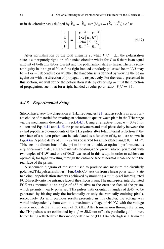
or in the circular basis defined by
E ± = |
E ± | exp(iφ ± ) = (
E x ±i
E y )/
√
2 as
⎡
⎢
⎢
⎣
I
Q
U
V
⎤
⎥
⎥
⎦ =
⎡
⎢
⎢
⎣
|E + |
2
+ |E − |
2
2Re
E + E
∗
−
−2Im
E + E
∗
−
|E + |
2
− |E − |
2
⎤
⎥
⎥
⎦ .
(4.17)
After normalisation by the total intensity I , when V /I = ±1 the polarisation
state is either purely right- or left-handed circular, whilst for V = 0 there is an equal
amount of both chiralities present and the polarisation state is linear. There is some
ambiguity in the sign of V , as for a right-handed circularly polarised beam V /I may
be +1 or −1 depending on whether the handedness is defined by viewing the beam
against or with the direction of propagation, respectively. For the results presented in
this section, we will define the polarisation state by observing against the direction
of propagation, such that for a right-handed circular polarisation V /I = +1.
4.4.3 Experimental Setup
Silicon has a very low dispersion at THz frequencies [21], and as such is an appropriate choice of material for creating an achromatic quater-wave plate in the THz range
via the mechanism described in Sect. 4.4.1. Using a refractive index n = 3.425 for
silicon and Eqs. 4.14 and 4.15, the phase advances and total phase delay between the
s- and p-polarised components of the THz pulses after total internal reflection at the
rear face of a silicon prism can be calculated as a function of θ i , and are shown in
Fig. 4.6a. A phase delay of δ = π/2 was observed for an incidence angle θ i = 41.9
◦ .
This sets the dimensions of the prism in order to achieve optimal performance as
a quarter-wave plate; a high-resistivity floating-zone grown silicon prism cut with
two angles of 41.9
◦ and one of 96.2
◦ was used in this setup, in order to achieve an
optimal θ i for light travelling through the entrance face at normal incidence onto the
rear face of the prism.
A schematic diagram of the setup used to produce and measure the circularly
polarised THz pulses is shown in Fig. 4.6b. Conversion from a linear polarisation state
to a circular polarisation state was achieved by mounting a multi-pixel interdigitated
PCE directly onto the entrance face of the silicon prism. The multi-pixel interdigitated
PCE was mounted at an angle of 45
◦ relative to the entrance face of the prism,
which permits linearly polarised THz pulses with orientation angles of ±45
◦ to be
generated by biasing only the horizontally or only the vertically emitting pixels,
respectively. As with previous results presented in this chapter, the voltage was
varied independently from zero to a maximum voltage of ±10 V, with the voltage
source modulated at a frequency of 50 kHz. After transmission through the prism,
the THz pulses were collimated by a f = 50.8 mm off-axis parabolic gold mirror,
before being reflected by a fluorine-doped tin oxide (FDTO)-coated-glass THz mirror
4 Scalable Interdigitated Photoconductive Emitters for the Electrical …
or in the circular basis defined by
E ± = |
E ± | exp(iφ ± ) = (
E x ±i
E y )/
√
2 as
⎡
⎢
⎢
⎣
I
Q
U
V
⎤
⎥
⎥
⎦ =
⎡
⎢
⎢
⎣
|E + |
2
+ |E − |
2
2Re
E + E
∗
−
−2Im
E + E
∗
−
|E + |
2
− |E − |
2
⎤
⎥
⎥
⎦ .
(4.17)
After normalisation by the total intensity I , when V /I = ±1 the polarisation
state is either purely right- or left-handed circular, whilst for V = 0 there is an equal
amount of both chiralities present and the polarisation state is linear. There is some
ambiguity in the sign of V , as for a right-handed circularly polarised beam V /I may
be +1 or −1 depending on whether the handedness is defined by viewing the beam
against or with the direction of propagation, respectively. For the results presented in
this section, we will define the polarisation state by observing against the direction
of propagation, such that for a right-handed circular polarisation V /I = +1.
4.4.3 Experimental Setup
Silicon has a very low dispersion at THz frequencies [21], and as such is an appropriate choice of material for creating an achromatic quater-wave plate in the THz range
via the mechanism described in Sect. 4.4.1. Using a refractive index n = 3.425 for
silicon and Eqs. 4.14 and 4.15, the phase advances and total phase delay between the
s- and p-polarised components of the THz pulses after total internal reflection at the
rear face of a silicon prism can be calculated as a function of θ i , and are shown in
Fig. 4.6a. A phase delay of δ = π/2 was observed for an incidence angle θ i = 41.9
◦ .
This sets the dimensions of the prism in order to achieve optimal performance as
a quarter-wave plate; a high-resistivity floating-zone grown silicon prism cut with
two angles of 41.9
◦ and one of 96.2
◦ was used in this setup, in order to achieve an
optimal θ i for light travelling through the entrance face at normal incidence onto the
rear face of the prism.
A schematic diagram of the setup used to produce and measure the circularly
polarised THz pulses is shown in Fig. 4.6b. Conversion from a linear polarisation state
to a circular polarisation state was achieved by mounting a multi-pixel interdigitated
PCE directly onto the entrance face of the silicon prism. The multi-pixel interdigitated
PCE was mounted at an angle of 45
◦ relative to the entrance face of the prism,
which permits linearly polarised THz pulses with orientation angles of ±45
◦ to be
generated by biasing only the horizontally or only the vertically emitting pixels,
respectively. As with previous results presented in this chapter, the voltage was
varied independently from zero to a maximum voltage of ±10 V, with the voltage
source modulated at a frequency of 50 kHz. After transmission through the prism,
the THz pulses were collimated by a f = 50.8 mm off-axis parabolic gold mirror,
before being reflected by a fluorine-doped tin oxide (FDTO)-coated-glass THz mirror