

2.1 Ideal Memristor: Basic Properties and Signatures
39
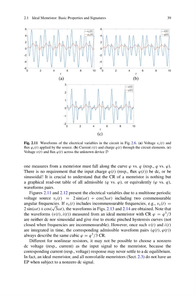
Fig. 2.11 Waveforms of the electrical variables in the circuit in Fig. 2.6. (a) Voltage v s (t) and
flux ϕ s (t) applied by the source. (b) Current i(t) and charge q(t) through the circuit elements. (c)
Voltage v(t) and flux ϕ(t) across the unknown device D
one measures from a memristor must fall along the curve ϕ vs. q (resp., q vs. ϕ).
There is no requirement that the input charge q(t) (resp., flux ϕ(t)) be dc, or be
sinusoidal! It is crucial to understand that the CR of a memristor is nothing but
a graphical read-out table of all admissible (q vs. ϕ), or equivalently (ϕ vs. q),
waveforms pairs.
Figures 2.11 and 2.12 present the electrical variables due to a multitone periodic
voltage source v s (t) = 2 sin(ωt) + cos(3ωt) including two commensurable
angular frequencies. If v s (t) includes incommensurable frequencies, e.g., v s (t) =
2 sin(ωt)+cos(
√
3ωt), the waveforms in Figs. 2.13 and 2.14 are obtained. Note that
the waveforms (v(t), i(t)) measured from an ideal memristor with CR ϕ = q 3 /3
are neither dc nor sinusoidal and give rise to exotic pinched hysteresis curves (not
closed when frequencies are incommensurable). However, once such v(t) and i(t)
are integrated in time, the corresponding admissible waveform pairs (q(t), ϕ(t))
always describe the same cubic ϕ = q 3 /3 CR.
Different for nonlinear resistors, it may not be possible to choose a nonzero
dc voltage (resp., current) as the input signal to the memristor, because the
corresponding current (resp., voltage) response may never settle to a dc equilibrium.
In fact, an ideal memristor, and all nonvolatile memristors (Sect. 2.3) do not have an
EP when subject to a nonzero dc signal.
39
Fig. 2.11 Waveforms of the electrical variables in the circuit in Fig. 2.6. (a) Voltage v s (t) and
flux ϕ s (t) applied by the source. (b) Current i(t) and charge q(t) through the circuit elements. (c)
Voltage v(t) and flux ϕ(t) across the unknown device D
one measures from a memristor must fall along the curve ϕ vs. q (resp., q vs. ϕ).
There is no requirement that the input charge q(t) (resp., flux ϕ(t)) be dc, or be
sinusoidal! It is crucial to understand that the CR of a memristor is nothing but
a graphical read-out table of all admissible (q vs. ϕ), or equivalently (ϕ vs. q),
waveforms pairs.
Figures 2.11 and 2.12 present the electrical variables due to a multitone periodic
voltage source v s (t) = 2 sin(ωt) + cos(3ωt) including two commensurable
angular frequencies. If v s (t) includes incommensurable frequencies, e.g., v s (t) =
2 sin(ωt)+cos(
√
3ωt), the waveforms in Figs. 2.13 and 2.14 are obtained. Note that
the waveforms (v(t), i(t)) measured from an ideal memristor with CR ϕ = q 3 /3
are neither dc nor sinusoidal and give rise to exotic pinched hysteresis curves (not
closed when frequencies are incommensurable). However, once such v(t) and i(t)
are integrated in time, the corresponding admissible waveform pairs (q(t), ϕ(t))
always describe the same cubic ϕ = q 3 /3 CR.
Different for nonlinear resistors, it may not be possible to choose a nonzero
dc voltage (resp., current) as the input signal to the memristor, because the
corresponding current (resp., voltage) response may never settle to a dc equilibrium.
In fact, an ideal memristor, and all nonvolatile memristors (Sect. 2.3) do not have an
EP when subject to a nonzero dc signal.