

11.5 State Equations and Nonlinear Dynamics
405
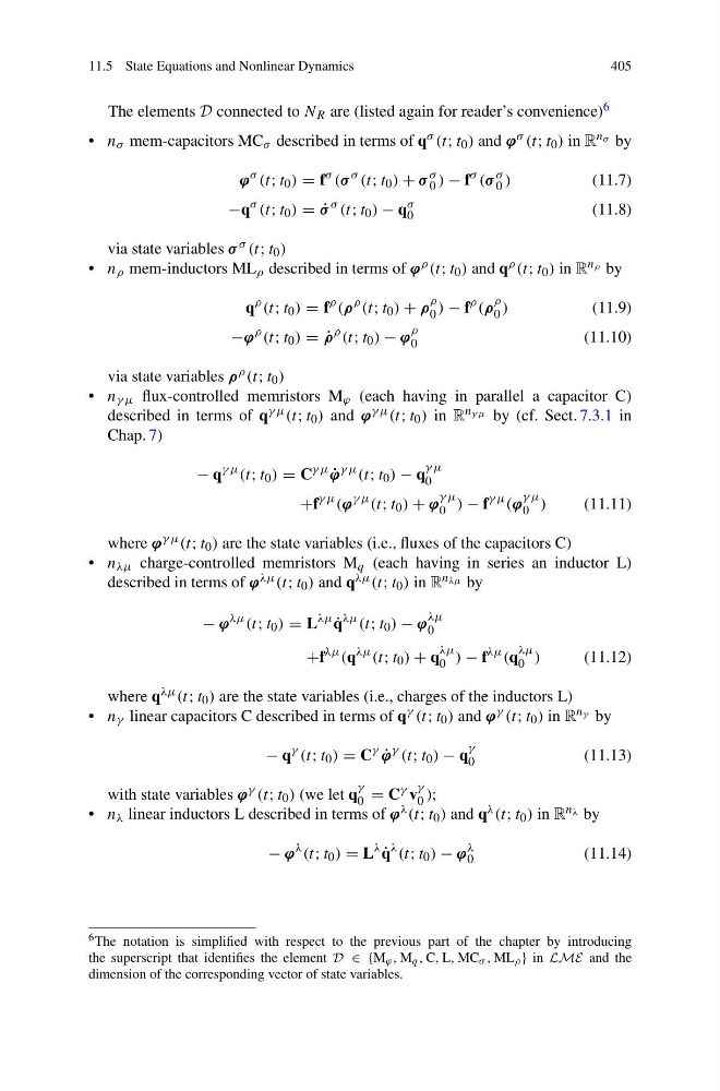
The elements D connected to N R are (listed again for reader’s convenience) 6
• n σ mem-capacitors MC σ described in terms of q σ (t; t 0 ) and ϕ σ (t; t 0 ) in R n σ by
ϕ
σ (t; t 0 ) = f
σ (σ
σ (t; t 0 ) + σ
σ
0 ) − f
σ (σ
σ
0 )
(11.7)
−q
σ (t; t 0 ) = ˙
σ
σ (t; t 0 ) − q
σ
0
(11.8)
via state variables σ σ (t; t 0 )
• n ρ mem-inductors ML ρ described in terms of ϕ ρ (t; t 0 ) and q ρ (t; t 0 ) in R n ρ by
q
ρ (t; t 0 ) = f
ρ (ρ
ρ (t; t 0 ) + ρ
ρ
0 ) − f
ρ (ρ
ρ
0 )
(11.9)
−ϕ
ρ (t; t 0 ) = ˙
ρ
ρ (t; t 0 ) − ϕ
ρ
0
(11.10)
via state variables ρ ρ (t; t 0 )
• n γ μ flux-controlled memristors M ϕ (each having in parallel a capacitor C)
described in terms of q γ μ (t; t 0 ) and ϕ γ μ (t; t 0 ) in R n γ μ by (cf. Sect. 7.3.1 in
Chap. 7)
− q
γ μ (t; t 0 ) = C
γ μ
˙
ϕ
γ μ (t; t 0 ) − q
γ μ
0
+f
γ μ (ϕ
γ μ (t; t 0 ) + ϕ
γ μ
0 ) − f
γ μ (ϕ
γ μ
0 )
(11.11)
where ϕ γ μ (t; t 0 ) are the state variables (i.e., fluxes of the capacitors C)
• n λμ charge-controlled memristors M q (each having in series an inductor L)
described in terms of ϕ λμ (t; t 0 ) and q λμ (t; t 0 ) in R n λμ by
− ϕ
λμ (t; t 0 ) = L
λμ
˙
q
λμ (t; t 0 ) − ϕ
λμ
0
+f
λμ (q
λμ (t; t 0 ) + q
λμ
0 ) − f
λμ (q
λμ
0 )
(11.12)
where q λμ (t; t 0 ) are the state variables (i.e., charges of the inductors L)
• n γ linear capacitors C described in terms of q γ (t; t 0 ) and ϕ γ (t; t 0 ) in R n γ by
− q
γ (t; t 0 ) = C
γ
˙
ϕ
γ (t; t 0 ) − q
γ
0
(11.13)
with state variables ϕ γ (t; t 0 ) (we let q
γ
0 = C γ v
γ
0 );
• n λ linear inductors L described in terms of ϕ λ (t; t 0 ) and q λ (t; t 0 ) in R n λ by
− ϕ
λ (t; t 0 ) = L
λ
˙
q
λ (t; t 0 ) − ϕ
λ
0
(11.14)
6 The notation is simplified with respect to the previous part of the chapter by introducing
the superscript that identifies the element D ∈ {M ϕ , M q , C, L, MC σ , ML ρ } in LME and the
dimension of the corresponding vector of state variables.
405
The elements D connected to N R are (listed again for reader’s convenience) 6
• n σ mem-capacitors MC σ described in terms of q σ (t; t 0 ) and ϕ σ (t; t 0 ) in R n σ by
ϕ
σ (t; t 0 ) = f
σ (σ
σ (t; t 0 ) + σ
σ
0 ) − f
σ (σ
σ
0 )
(11.7)
−q
σ (t; t 0 ) = ˙
σ
σ (t; t 0 ) − q
σ
0
(11.8)
via state variables σ σ (t; t 0 )
• n ρ mem-inductors ML ρ described in terms of ϕ ρ (t; t 0 ) and q ρ (t; t 0 ) in R n ρ by
q
ρ (t; t 0 ) = f
ρ (ρ
ρ (t; t 0 ) + ρ
ρ
0 ) − f
ρ (ρ
ρ
0 )
(11.9)
−ϕ
ρ (t; t 0 ) = ˙
ρ
ρ (t; t 0 ) − ϕ
ρ
0
(11.10)
via state variables ρ ρ (t; t 0 )
• n γ μ flux-controlled memristors M ϕ (each having in parallel a capacitor C)
described in terms of q γ μ (t; t 0 ) and ϕ γ μ (t; t 0 ) in R n γ μ by (cf. Sect. 7.3.1 in
Chap. 7)
− q
γ μ (t; t 0 ) = C
γ μ
˙
ϕ
γ μ (t; t 0 ) − q
γ μ
0
+f
γ μ (ϕ
γ μ (t; t 0 ) + ϕ
γ μ
0 ) − f
γ μ (ϕ
γ μ
0 )
(11.11)
where ϕ γ μ (t; t 0 ) are the state variables (i.e., fluxes of the capacitors C)
• n λμ charge-controlled memristors M q (each having in series an inductor L)
described in terms of ϕ λμ (t; t 0 ) and q λμ (t; t 0 ) in R n λμ by
− ϕ
λμ (t; t 0 ) = L
λμ
˙
q
λμ (t; t 0 ) − ϕ
λμ
0
+f
λμ (q
λμ (t; t 0 ) + q
λμ
0 ) − f
λμ (q
λμ
0 )
(11.12)
where q λμ (t; t 0 ) are the state variables (i.e., charges of the inductors L)
• n γ linear capacitors C described in terms of q γ (t; t 0 ) and ϕ γ (t; t 0 ) in R n γ by
− q
γ (t; t 0 ) = C
γ
˙
ϕ
γ (t; t 0 ) − q
γ
0
(11.13)
with state variables ϕ γ (t; t 0 ) (we let q
γ
0 = C γ v
γ
0 );
• n λ linear inductors L described in terms of ϕ λ (t; t 0 ) and q λ (t; t 0 ) in R n λ by
− ϕ
λ (t; t 0 ) = L
λ
˙
q
λ (t; t 0 ) − ϕ
λ
0
(11.14)
6 The notation is simplified with respect to the previous part of the chapter by introducing
the superscript that identifies the element D ∈ {M ϕ , M q , C, L, MC σ , ML ρ } in LME and the
dimension of the corresponding vector of state variables.