

402
11 Nonlinear Dynamics of Circuits with Mem-Elements
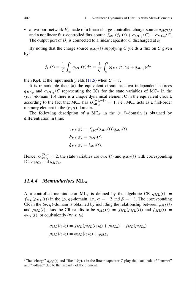
• a two-port network B c made of a linear charge-controlled charge-source q MC (t)
and a nonlinear flux-controlled flux-source f MC ( ˆ
ϕ C (t) + σ MC 0 /C) − σ MC 0 /C.
The output port of B c is connected to a linear capacitor C discharged at t 0 .
By noting that the charge source q MC (t) supplying C yields a flux on C given
by 5
ˆ
ϕ C (t) =
1
C
t
t 0
q MC (τ )dτ =
1
C
t
t 0
(q MC (τ, t 0 ) + q MC 0 )dτ
then KϕL at the input mesh yields (11.5) when C = 1.
It is remarkable that: (a) the equivalent circuit has two independent sources
q MC 0 and σ MC 0 /C representing the ICs for the state variables of MC σ in the
(v, i)-domain; (b) there is a unique dynamical element C in the equivalent circuit,
according to the fact that MC σ has O
(−1,−1)
MC σ
= 1, i.e., MC σ acts as a first-order
memory element in the (ϕ, q)-domain.
The following description of a MC σ in the (v, i)-domain is obtained by
differentiation in time:
v MC (t) = f
MC (σ MC (t))q MC (t)
˙
σ MC (t) = q MC (t)
˙
q MC (t) = i MC (t).
Hence, O
(0,0)
MC σ
= 2, the state variables are σ MC (t) and q MC (t) with corresponding
ICs σ MC 0 and q MC 0 .
11.4.4 Meminductors ML ρ
A ρ-controlled meminductor ML ρ is defined by the algebraic CR q ML (t) =
f ML (ρ ML (t)) in the (ρ, q)-domain, i.e., α = −2 and β = −1. The corresponding
CR in the (ϕ, q)-domain is obtained by including the relationship between ϕ ML (t)
and ρ ML (t), thus the CR results to be q ML (t) = f ML (ρ ML (t)) and ˙
ρ ML (t) =
ϕ ML (t), or equivalently (∀t ≥ t 0 )
q ML (t; t 0 ) = f ML (ρ ML (t; t 0 ) + ρ ML 0 ) − f ML (ρ ML 0 )
˙
ρ ML (t; t 0 ) = ϕ ML (t; t 0 ) + ϕ ML 0
5 The “charge” q MC (t) and “flux” ˆ
ϕ C (t) in the linear capacitor C play the usual role of “current”
and “voltage” due to the linearity of the element.
11 Nonlinear Dynamics of Circuits with Mem-Elements
• a two-port network B c made of a linear charge-controlled charge-source q MC (t)
and a nonlinear flux-controlled flux-source f MC ( ˆ
ϕ C (t) + σ MC 0 /C) − σ MC 0 /C.
The output port of B c is connected to a linear capacitor C discharged at t 0 .
By noting that the charge source q MC (t) supplying C yields a flux on C given
by 5
ˆ
ϕ C (t) =
1
C
t
t 0
q MC (τ )dτ =
1
C
t
t 0
(q MC (τ, t 0 ) + q MC 0 )dτ
then KϕL at the input mesh yields (11.5) when C = 1.
It is remarkable that: (a) the equivalent circuit has two independent sources
q MC 0 and σ MC 0 /C representing the ICs for the state variables of MC σ in the
(v, i)-domain; (b) there is a unique dynamical element C in the equivalent circuit,
according to the fact that MC σ has O
(−1,−1)
MC σ
= 1, i.e., MC σ acts as a first-order
memory element in the (ϕ, q)-domain.
The following description of a MC σ in the (v, i)-domain is obtained by
differentiation in time:
v MC (t) = f
MC (σ MC (t))q MC (t)
˙
σ MC (t) = q MC (t)
˙
q MC (t) = i MC (t).
Hence, O
(0,0)
MC σ
= 2, the state variables are σ MC (t) and q MC (t) with corresponding
ICs σ MC 0 and q MC 0 .
11.4.4 Meminductors ML ρ
A ρ-controlled meminductor ML ρ is defined by the algebraic CR q ML (t) =
f ML (ρ ML (t)) in the (ρ, q)-domain, i.e., α = −2 and β = −1. The corresponding
CR in the (ϕ, q)-domain is obtained by including the relationship between ϕ ML (t)
and ρ ML (t), thus the CR results to be q ML (t) = f ML (ρ ML (t)) and ˙
ρ ML (t) =
ϕ ML (t), or equivalently (∀t ≥ t 0 )
q ML (t; t 0 ) = f ML (ρ ML (t; t 0 ) + ρ ML 0 ) − f ML (ρ ML 0 )
˙
ρ ML (t; t 0 ) = ϕ ML (t; t 0 ) + ϕ ML 0
5 The “charge” q MC (t) and “flux” ˆ
ϕ C (t) in the linear capacitor C play the usual role of “current”
and “voltage” due to the linearity of the element.