

11.4 Constitutive Relations of Two-Terminal Elements in LME
401
and then O
(0,0)
M q
= 1 and the state variable is q M (t). The IC is q M 0 .
11.4.3 Memcapacitor MC σ
A σ -controlled memcapacitor MC σ is defined by the algebraic CR ϕ MC (t) =
f MC (σ MC (t)) in the (ϕ, σ )-domain, i.e., α = −1 and β = −2. The corresponding
CR in the (ϕ, q)-domain is obtained by including the relationship between σ MC (t)
and q MC (t), thus the CR results to be ϕ MC (t) = f MC (σ MC (t)) and ˙
σ MC (t) =
q MC (t), or equivalently (∀t ≥ t 0 )
ϕ MC (t; t 0 ) = f MC (σ MC (t; t 0 ) + σ MC 0 ) − f MC (σ MC 0 )
˙
σ MC (t; t 0 ) = q MC (t; t 0 ) + q MC 0
where σ MC 0 = σ MC (t 0 ) and q MC 0 = q MC (t 0 ). Hence, O
(−1,−1)
MC σ
= 1, the state
variable is σ MC (t; t 0 ) = σ MC (t) − σ MC 0 and the IC is σ MC (t 0 ; t 0 ) = 0. It is worth
noting that the CR depends upon σ MC 0 and q MC 0 .
We can also write
ϕ MC (t; t 0 ) = f MC
σ MC 0 +
t
t 0
q MC (τ ; t 0 ) + q MC 0
dτ
− f MC (σ MC 0 ) (11.5)
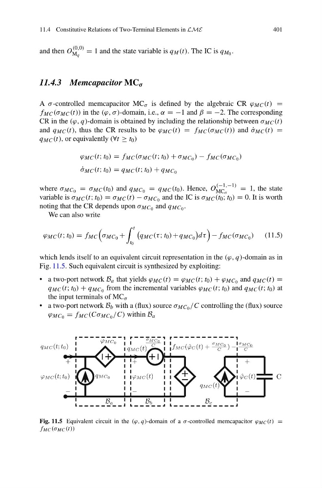
which lends itself to an equivalent circuit representation in the (ϕ, q)-domain as in
Fig. 11.5. Such equivalent circuit is synthesized by exploiting:
• a two-port network B a that yields ϕ MC (t) = ϕ MC (t; t 0 ) + ϕ MC 0 and q MC (t) =
q MC (t; t 0 ) + q MC 0 from the incremental variables ϕ MC (t; t 0 ) and q MC (t; t 0 ) at
the input terminals of MC σ
• a two-port network B b with a (flux) source σ MC 0 /C controlling the (flux) source
ϕ MC 0 = f MC (Cσ MC 0 /C) within B a
qMC 0
ϕMC 0
σ MC 0
C
fMC( ˆ
ϕC (t) +
σ MC 0
C
) −
σ MC 0
C
qMC(t)
C
+
−
ˆ
ϕC (t)
B a
B b
B c
qMC(t; t0)
qMC(t)
+
−
ϕMC(t)
+
−
ϕMC(t; t0)
Fig. 11.5 Equivalent circuit in the (ϕ, q)-domain of a σ -controlled memcapacitor ϕ MC (t) =
f MC (σ MC (t))
401
and then O
(0,0)
M q
= 1 and the state variable is q M (t). The IC is q M 0 .
11.4.3 Memcapacitor MC σ
A σ -controlled memcapacitor MC σ is defined by the algebraic CR ϕ MC (t) =
f MC (σ MC (t)) in the (ϕ, σ )-domain, i.e., α = −1 and β = −2. The corresponding
CR in the (ϕ, q)-domain is obtained by including the relationship between σ MC (t)
and q MC (t), thus the CR results to be ϕ MC (t) = f MC (σ MC (t)) and ˙
σ MC (t) =
q MC (t), or equivalently (∀t ≥ t 0 )
ϕ MC (t; t 0 ) = f MC (σ MC (t; t 0 ) + σ MC 0 ) − f MC (σ MC 0 )
˙
σ MC (t; t 0 ) = q MC (t; t 0 ) + q MC 0
where σ MC 0 = σ MC (t 0 ) and q MC 0 = q MC (t 0 ). Hence, O
(−1,−1)
MC σ
= 1, the state
variable is σ MC (t; t 0 ) = σ MC (t) − σ MC 0 and the IC is σ MC (t 0 ; t 0 ) = 0. It is worth
noting that the CR depends upon σ MC 0 and q MC 0 .
We can also write
ϕ MC (t; t 0 ) = f MC
σ MC 0 +
t
t 0
q MC (τ ; t 0 ) + q MC 0
dτ
− f MC (σ MC 0 ) (11.5)
which lends itself to an equivalent circuit representation in the (ϕ, q)-domain as in
Fig. 11.5. Such equivalent circuit is synthesized by exploiting:
• a two-port network B a that yields ϕ MC (t) = ϕ MC (t; t 0 ) + ϕ MC 0 and q MC (t) =
q MC (t; t 0 ) + q MC 0 from the incremental variables ϕ MC (t; t 0 ) and q MC (t; t 0 ) at
the input terminals of MC σ
• a two-port network B b with a (flux) source σ MC 0 /C controlling the (flux) source
ϕ MC 0 = f MC (Cσ MC 0 /C) within B a
qMC 0
ϕMC 0
σ MC 0
C
fMC( ˆ
ϕC (t) +
σ MC 0
C
) −
σ MC 0
C
qMC(t)
C
+
−
ˆ
ϕC (t)
B a
B b
B c
qMC(t; t0)
qMC(t)
+
−
ϕMC(t)
+
−
ϕMC(t; t0)
Fig. 11.5 Equivalent circuit in the (ϕ, q)-domain of a σ -controlled memcapacitor ϕ MC (t) =
f MC (σ MC (t))