

380
10 Extended Memristor Devices
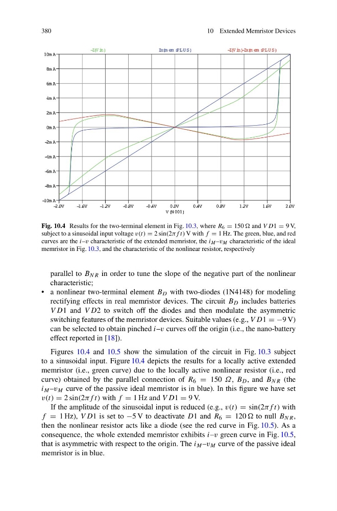
Fig. 10.4 Results for the two-terminal element in Fig. 10.3, where R 6 = 150 and V D1 = 9 V,
subject to a sinusoidal input voltage v(t) = 2 sin(2πf t) V with f = 1 Hz. The green, blue, and red
curves are the i–v characteristic of the extended memristor, the i M –v M characteristic of the ideal
memristor in Fig. 10.3, and the characteristic of the nonlinear resistor, respectively
parallel to B NR in order to tune the slope of the negative part of the nonlinear
characteristic;
• a nonlinear two-terminal element B D with two-diodes (1N4148) for modeling
rectifying effects in real memristor devices. The circuit B D includes batteries
V D1 and V D2 to switch off the diodes and then modulate the asymmetric
switching features of the memristor devices. Suitable values (e.g., V D1 = −9 V)
can be selected to obtain pinched i–v curves off the origin (i.e., the nano-battery
effect reported in [18]).
Figures 10.4 and 10.5 show the simulation of the circuit in Fig. 10.3 subject
to a sinusoidal input. Figure 10.4 depicts the results for a locally active extended
memristor (i.e., green curve) due to the locally active nonlinear resistor (i.e., red
curve) obtained by the parallel connection of R 6 = 150 Ω, B D , and B NR (the
i M –v M curve of the passive ideal memristor is in blue). In this figure we have set
v(t) = 2 sin(2πf t) with f = 1 Hz and V D1 = 9 V.
If the amplitude of the sinusoidal input is reduced (e.g., v(t) = sin(2πf t) with
f = 1 Hz), V D1 is set to −5 V to deactivate D1 and R 6 = 120 to null B NR ,
then the nonlinear resistor acts like a diode (see the red curve in Fig. 10.5). As a
consequence, the whole extended memristor exhibits i–v green curve in Fig. 10.5,
that is asymmetric with respect to the origin. The i M –v M curve of the passive ideal
memristor is in blue.
10 Extended Memristor Devices
Fig. 10.4 Results for the two-terminal element in Fig. 10.3, where R 6 = 150 and V D1 = 9 V,
subject to a sinusoidal input voltage v(t) = 2 sin(2πf t) V with f = 1 Hz. The green, blue, and red
curves are the i–v characteristic of the extended memristor, the i M –v M characteristic of the ideal
memristor in Fig. 10.3, and the characteristic of the nonlinear resistor, respectively
parallel to B NR in order to tune the slope of the negative part of the nonlinear
characteristic;
• a nonlinear two-terminal element B D with two-diodes (1N4148) for modeling
rectifying effects in real memristor devices. The circuit B D includes batteries
V D1 and V D2 to switch off the diodes and then modulate the asymmetric
switching features of the memristor devices. Suitable values (e.g., V D1 = −9 V)
can be selected to obtain pinched i–v curves off the origin (i.e., the nano-battery
effect reported in [18]).
Figures 10.4 and 10.5 show the simulation of the circuit in Fig. 10.3 subject
to a sinusoidal input. Figure 10.4 depicts the results for a locally active extended
memristor (i.e., green curve) due to the locally active nonlinear resistor (i.e., red
curve) obtained by the parallel connection of R 6 = 150 Ω, B D , and B NR (the
i M –v M curve of the passive ideal memristor is in blue). In this figure we have set
v(t) = 2 sin(2πf t) with f = 1 Hz and V D1 = 9 V.
If the amplitude of the sinusoidal input is reduced (e.g., v(t) = sin(2πf t) with
f = 1 Hz), V D1 is set to −5 V to deactivate D1 and R 6 = 120 to null B NR ,
then the nonlinear resistor acts like a diode (see the red curve in Fig. 10.5). As a
consequence, the whole extended memristor exhibits i–v green curve in Fig. 10.5,
that is asymmetric with respect to the origin. The i M –v M curve of the passive ideal
memristor is in blue.