

10.1 A Class of Extended Memristors
379
10.1.1 Examples of Extended Memristors
This section reports some selected examples of an extended memristor D ext as in
Fig. 10.1 obtained by combining an ideal memristor with a circuit implementing a
(locally active) nonlinear resistor. The goal is to show how the parameters of the
nonlinear resistor can be massaged to capture the features of the experimental i–v
curves observed during the characterization of real memristor devices. Simulations
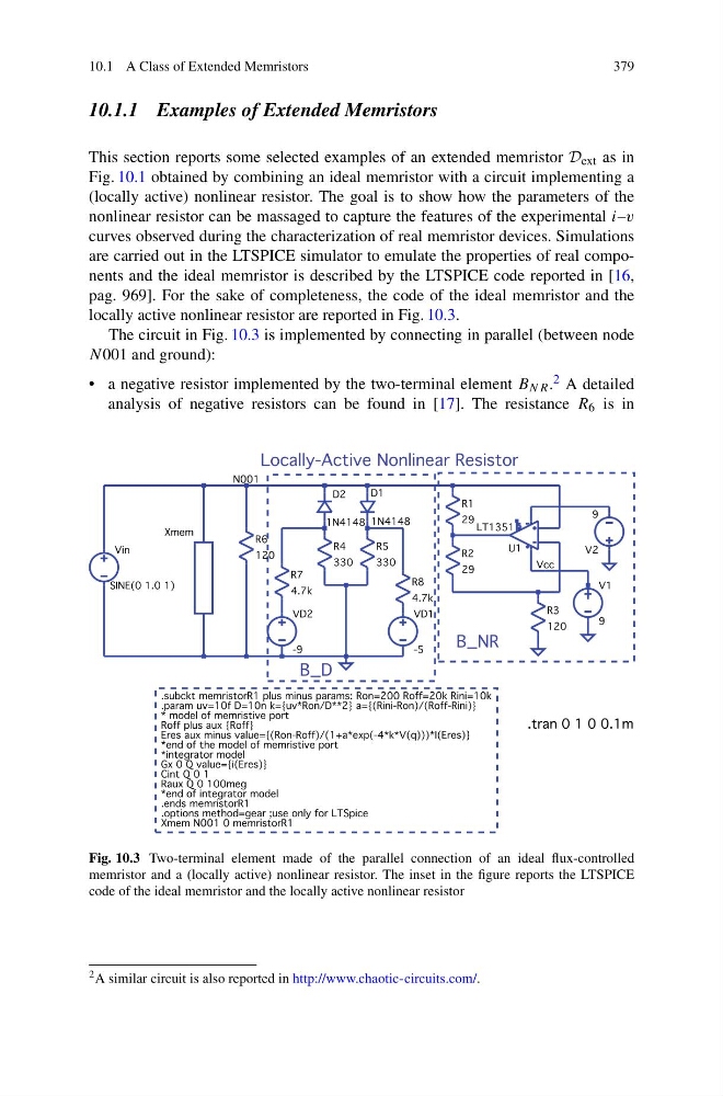
are carried out in the LTSPICE simulator to emulate the properties of real components and the ideal memristor is described by the LTSPICE code reported in [16,
pag. 969]. For the sake of completeness, the code of the ideal memristor and the
locally active nonlinear resistor are reported in Fig. 10.3.
The circuit in Fig. 10.3 is implemented by connecting in parallel (between node
N001 and ground):
• a negative resistor implemented by the two-terminal element B NR . 2 A detailed
analysis of negative resistors can be found in [17]. The resistance R 6 is in
Fig. 10.3 Two-terminal element made of the parallel connection of an ideal flux-controlled
memristor and a (locally active) nonlinear resistor. The inset in the figure reports the LTSPICE
code of the ideal memristor and the locally active nonlinear resistor
2 A similar circuit is also reported in http://www.chaotic-circuits.com/.
379
10.1.1 Examples of Extended Memristors
This section reports some selected examples of an extended memristor D ext as in
Fig. 10.1 obtained by combining an ideal memristor with a circuit implementing a
(locally active) nonlinear resistor. The goal is to show how the parameters of the
nonlinear resistor can be massaged to capture the features of the experimental i–v
curves observed during the characterization of real memristor devices. Simulations
are carried out in the LTSPICE simulator to emulate the properties of real components and the ideal memristor is described by the LTSPICE code reported in [16,
pag. 969]. For the sake of completeness, the code of the ideal memristor and the
locally active nonlinear resistor are reported in Fig. 10.3.
The circuit in Fig. 10.3 is implemented by connecting in parallel (between node
N001 and ground):
• a negative resistor implemented by the two-terminal element B NR . 2 A detailed
analysis of negative resistors can be found in [17]. The resistance R 6 is in
Fig. 10.3 Two-terminal element made of the parallel connection of an ideal flux-controlled
memristor and a (locally active) nonlinear resistor. The inset in the figure reports the LTSPICE
code of the ideal memristor and the locally active nonlinear resistor
2 A similar circuit is also reported in http://www.chaotic-circuits.com/.