

378
10 Extended Memristor Devices
F R (v) = I S
exp(
v
ηV T
) − 1
(10.11)
where I S is the reverse bias saturation current, V T is the thermal voltage, and η is
the ideality factor. By considering a cubic ideal memristor q M = f (ϕ M ) = aϕ M +
1
3 bϕ 3
M , the memconductance
G(ϕ M , v) =
I S
exp(
v
ηV T
) − 1
v
+ a + bϕ
2
M
as in (10.10) is obtained. By De l’Hôpital rule, for any ϕ M ∈ R, we have
lim
v→0
G(ϕ M , v) =
I S
ηV T
+ a + bϕ
2
M
hence the memductance is bounded in a neighborhood of (ϕ M , v) = (ϕ M , 0). The
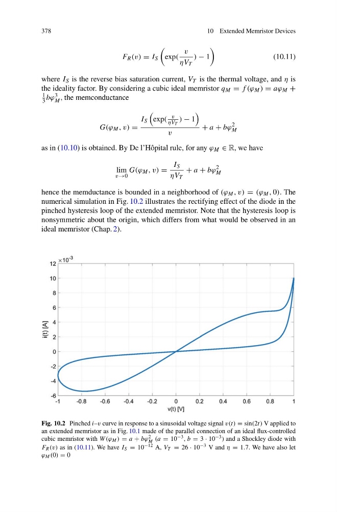
numerical simulation in Fig. 10.2 illustrates the rectifying effect of the diode in the
pinched hysteresis loop of the extended memristor. Note that the hysteresis loop is
nonsymmetric about the origin, which differs from what would be observed in an
ideal memristor (Chap. 2).
Fig. 10.2 Pinched i–v curve in response to a sinusoidal voltage signal v(t) = sin(2t) V applied to
an extended memristor as in Fig. 10.1 made of the parallel connection of an ideal flux-controlled
cubic memristor with W (ϕ M ) = a + bϕ 2
M (a = 10 −3 , b = 3 · 10 −3 ) and a Shockley diode with
F R (v) as in (10.11). We have I S = 10 −12 A, V T = 26 · 10 −3 V and η = 1.7. We have also let
ϕ M (0) = 0
10 Extended Memristor Devices
F R (v) = I S
exp(
v
ηV T
) − 1
(10.11)
where I S is the reverse bias saturation current, V T is the thermal voltage, and η is
the ideality factor. By considering a cubic ideal memristor q M = f (ϕ M ) = aϕ M +
1
3 bϕ 3
M , the memconductance
G(ϕ M , v) =
I S
exp(
v
ηV T
) − 1
v
+ a + bϕ
2
M
as in (10.10) is obtained. By De l’Hôpital rule, for any ϕ M ∈ R, we have
lim
v→0
G(ϕ M , v) =
I S
ηV T
+ a + bϕ
2
M
hence the memductance is bounded in a neighborhood of (ϕ M , v) = (ϕ M , 0). The
numerical simulation in Fig. 10.2 illustrates the rectifying effect of the diode in the
pinched hysteresis loop of the extended memristor. Note that the hysteresis loop is
nonsymmetric about the origin, which differs from what would be observed in an
ideal memristor (Chap. 2).
Fig. 10.2 Pinched i–v curve in response to a sinusoidal voltage signal v(t) = sin(2t) V applied to
an extended memristor as in Fig. 10.1 made of the parallel connection of an ideal flux-controlled
cubic memristor with W (ϕ M ) = a + bϕ 2
M (a = 10 −3 , b = 3 · 10 −3 ) and a Shockley diode with
F R (v) as in (10.11). We have I S = 10 −12 A, V T = 26 · 10 −3 V and η = 1.7. We have also let
ϕ M (0) = 0