

10.1 A Class of Extended Memristors
381
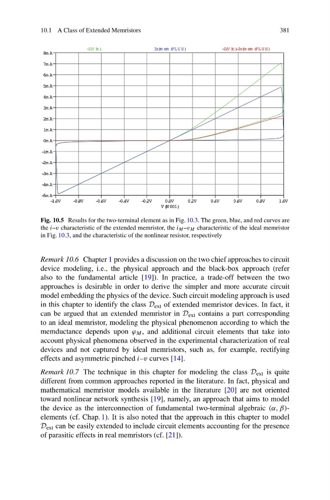
Fig. 10.5 Results for the two-terminal element as in Fig. 10.3. The green, blue, and red curves are
the i–v characteristic of the extended memristor, the i M –v M characteristic of the ideal memristor
in Fig. 10.3, and the characteristic of the nonlinear resistor, respectively
Remark 10.6 Chapter 1 provides a discussion on the two chief approaches to circuit
device modeling, i.e., the physical approach and the black-box approach (refer
also to the fundamental article [19]). In practice, a trade-off between the two
approaches is desirable in order to derive the simpler and more accurate circuit
model embedding the physics of the device. Such circuit modeling approach is used
in this chapter to identify the class D ext of extended memristor devices. In fact, it
can be argued that an extended memristor in D ext contains a part corresponding
to an ideal memristor, modeling the physical phenomenon according to which the
memductance depends upon ϕ M , and additional circuit elements that take into
account physical phenomena observed in the experimental characterization of real
devices and not captured by ideal memristors, such as, for example, rectifying
effects and asymmetric pinched i–v curves [14].
Remark 10.7 The technique in this chapter for modeling the class D ext is quite
different from common approaches reported in the literature. In fact, physical and
mathematical memristor models available in the literature [20] are not oriented
toward nonlinear network synthesis [19], namely, an approach that aims to model
the device as the interconnection of fundamental two-terminal algebraic (α, β)elements (cf. Chap. 1). It is also noted that the approach in this chapter to model
D ext can be easily extended to include circuit elements accounting for the presence
of parasitic effects in real memristors (cf. [21]).
381
Fig. 10.5 Results for the two-terminal element as in Fig. 10.3. The green, blue, and red curves are
the i–v characteristic of the extended memristor, the i M –v M characteristic of the ideal memristor
in Fig. 10.3, and the characteristic of the nonlinear resistor, respectively
Remark 10.6 Chapter 1 provides a discussion on the two chief approaches to circuit
device modeling, i.e., the physical approach and the black-box approach (refer
also to the fundamental article [19]). In practice, a trade-off between the two
approaches is desirable in order to derive the simpler and more accurate circuit
model embedding the physics of the device. Such circuit modeling approach is used
in this chapter to identify the class D ext of extended memristor devices. In fact, it
can be argued that an extended memristor in D ext contains a part corresponding
to an ideal memristor, modeling the physical phenomenon according to which the
memductance depends upon ϕ M , and additional circuit elements that take into
account physical phenomena observed in the experimental characterization of real
devices and not captured by ideal memristors, such as, for example, rectifying
effects and asymmetric pinched i–v curves [14].
Remark 10.7 The technique in this chapter for modeling the class D ext is quite
different from common approaches reported in the literature. In fact, physical and
mathematical memristor models available in the literature [20] are not oriented
toward nonlinear network synthesis [19], namely, an approach that aims to model
the device as the interconnection of fundamental two-terminal algebraic (α, β)elements (cf. Chap. 1). It is also noted that the approach in this chapter to model
D ext can be easily extended to include circuit elements accounting for the presence
of parasitic effects in real memristors (cf. [21]).