

7.4 State Equations in the Flux-Charge Domain
287
7.4.1 Class N D
N R of Memristor Circuits
Suppose that (A1)–(A3) are satisfied, hence the memristor circuit N is made of the
(n C + n L )-port N R connected to the n C elements D ϕ and to the n L elements D q .
In this case, (A1) is equivalent to the following topological assumption that can
be easily checked by inspection: the memristor network N has no loops made by
capacitors and/or flux sources and no cut-sets made by inductors and/or charge
sources.
Summing up, the case we are going to analyze in detail is that where any fluxcontrolled (resp., charge-controlled) memristor of N is in parallel to a capacitor
(resp., in series with an inductor); moreover, any negative resistor is either in
parallel to a capacitor or in series with an inductor. Recall that, by construction,
the adynamic network N R contains only positive resistors and/or independent flux
or charge sources.
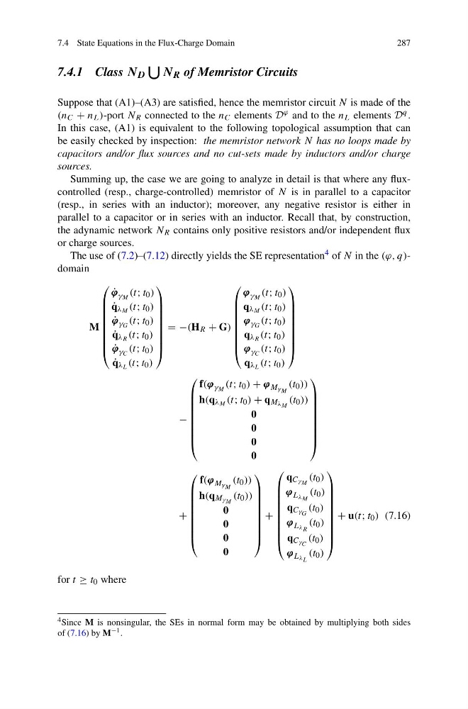
The use of (7.2)–(7.12) directly yields the SE representation 4 of N in the (ϕ, q)domain
M
⎛
⎜
⎜
⎜
⎜
⎜
⎜
⎜
⎝
˙
ϕ γ M (t; t 0 )
˙
q λ M (t; t 0 )
˙
ϕ γ G (t; t 0 )
˙
q λ R (t; t 0 )
˙
ϕ γ C (t; t 0 )
˙
q λ L (t; t 0 )
⎞
⎟
⎟
⎟
⎟
⎟
⎟
⎟
⎠
= −(H R + G)
⎛
⎜
⎜
⎜
⎜
⎜
⎜
⎜
⎝
ϕ γ M (t; t 0 )
q λ M (t; t 0 )
ϕ γ G (t; t 0 )
q λ R (t; t 0 )
ϕ γ C (t; t 0 )
q λ L (t; t 0 )
⎞
⎟
⎟
⎟
⎟
⎟
⎟
⎟
⎠
−
⎛
⎜
⎜
⎜
⎜
⎜
⎜
⎜
⎝
f(ϕ γ M (t; t 0 ) + ϕ M γ M
(t 0 ))
h(q λ M (t; t 0 ) + q M λ M (t 0 ))
0
0
0
0
⎞
⎟
⎟
⎟
⎟
⎟
⎟
⎟
⎠
+
⎛
⎜
⎜
⎜
⎜
⎜
⎜
⎜
⎝
f(ϕ M γ M
(t 0 ))
h(q M γ M (t 0 ))
0
0
0
0
⎞
⎟
⎟
⎟
⎟
⎟
⎟
⎟
⎠
+
⎛
⎜
⎜
⎜
⎜
⎜
⎜
⎜
⎜
⎝
q C γ M (t 0 )
ϕ L λ M
(t 0 )
q C γ G (t 0 )
ϕ L λ R
(t 0 )
q C γ C (t 0 )
ϕ L λ L
(t 0 )
⎞
⎟
⎟
⎟
⎟
⎟
⎟
⎟
⎟
⎠
+ u(t; t 0 ) (7.16)
for t ≥ t 0 where
4 Since M is nonsingular, the SEs in normal form may be obtained by multiplying both sides
of (7.16) by M −1 .
287
7.4.1 Class N D
N R of Memristor Circuits
Suppose that (A1)–(A3) are satisfied, hence the memristor circuit N is made of the
(n C + n L )-port N R connected to the n C elements D ϕ and to the n L elements D q .
In this case, (A1) is equivalent to the following topological assumption that can
be easily checked by inspection: the memristor network N has no loops made by
capacitors and/or flux sources and no cut-sets made by inductors and/or charge
sources.
Summing up, the case we are going to analyze in detail is that where any fluxcontrolled (resp., charge-controlled) memristor of N is in parallel to a capacitor
(resp., in series with an inductor); moreover, any negative resistor is either in
parallel to a capacitor or in series with an inductor. Recall that, by construction,
the adynamic network N R contains only positive resistors and/or independent flux
or charge sources.
The use of (7.2)–(7.12) directly yields the SE representation 4 of N in the (ϕ, q)domain
M
⎛
⎜
⎜
⎜
⎜
⎜
⎜
⎜
⎝
˙
ϕ γ M (t; t 0 )
˙
q λ M (t; t 0 )
˙
ϕ γ G (t; t 0 )
˙
q λ R (t; t 0 )
˙
ϕ γ C (t; t 0 )
˙
q λ L (t; t 0 )
⎞
⎟
⎟
⎟
⎟
⎟
⎟
⎟
⎠
= −(H R + G)
⎛
⎜
⎜
⎜
⎜
⎜
⎜
⎜
⎝
ϕ γ M (t; t 0 )
q λ M (t; t 0 )
ϕ γ G (t; t 0 )
q λ R (t; t 0 )
ϕ γ C (t; t 0 )
q λ L (t; t 0 )
⎞
⎟
⎟
⎟
⎟
⎟
⎟
⎟
⎠
−
⎛
⎜
⎜
⎜
⎜
⎜
⎜
⎜
⎝
f(ϕ γ M (t; t 0 ) + ϕ M γ M
(t 0 ))
h(q λ M (t; t 0 ) + q M λ M (t 0 ))
0
0
0
0
⎞
⎟
⎟
⎟
⎟
⎟
⎟
⎟
⎠
+
⎛
⎜
⎜
⎜
⎜
⎜
⎜
⎜
⎝
f(ϕ M γ M
(t 0 ))
h(q M γ M (t 0 ))
0
0
0
0
⎞
⎟
⎟
⎟
⎟
⎟
⎟
⎟
⎠
+
⎛
⎜
⎜
⎜
⎜
⎜
⎜
⎜
⎜
⎝
q C γ M (t 0 )
ϕ L λ M
(t 0 )
q C γ G (t 0 )
ϕ L λ R
(t 0 )
q C γ C (t 0 )
ϕ L λ L
(t 0 )
⎞
⎟
⎟
⎟
⎟
⎟
⎟
⎟
⎟
⎠
+ u(t; t 0 ) (7.16)
for t ≥ t 0 where
4 Since M is nonsingular, the SEs in normal form may be obtained by multiplying both sides
of (7.16) by M −1 .