

5.8 Formulation of Memristor Circuits Equations
211
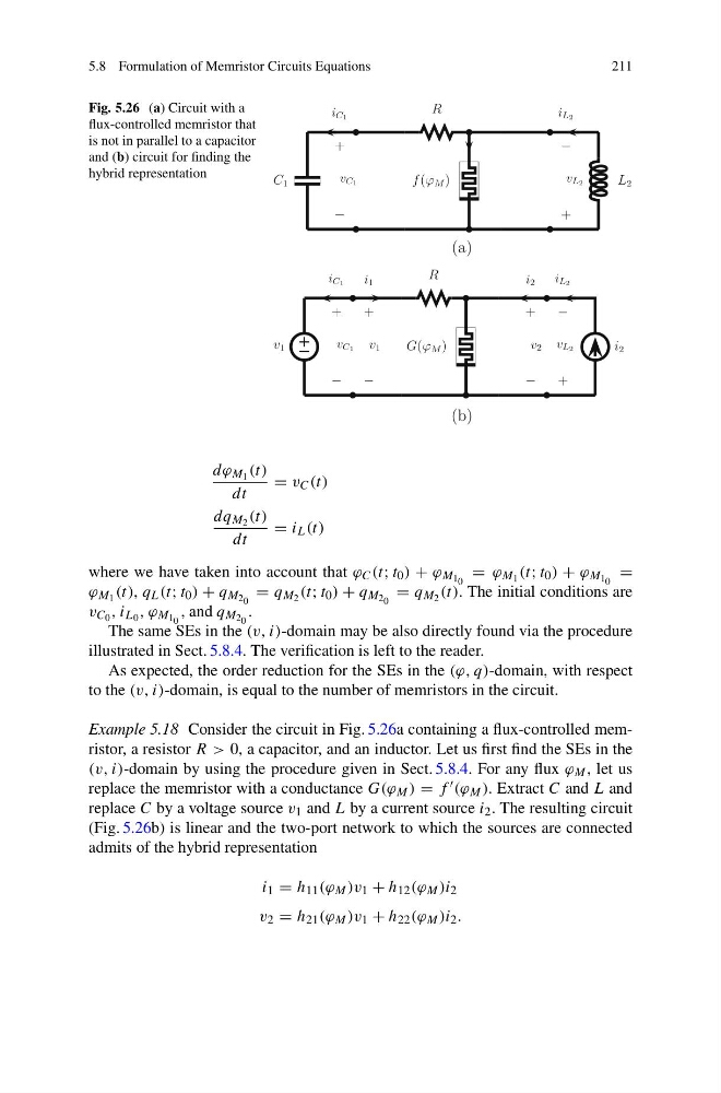
Fig. 5.26 (a) Circuit with a
flux-controlled memristor that
is not in parallel to a capacitor
and (b) circuit for finding the
hybrid representation
C 1
L 2
R
f (ϕ M )
(a)
(b)
v C1
i C1
+
−
v L2
i L2
−
+
v 1
i 2
R
G(ϕ M )
+
−
v 1
i 1
v C1
i C1
+
−
+
−
v 2
i 2
v L2
i L2
−
+
dϕ M 1 (t)
dt
= v C (t)
dq M 2 (t)
dt
= i L (t)
where we have taken into account that ϕ C (t; t 0 ) + ϕ M 1 0 = ϕ M 1 (t; t 0 ) + ϕ M 1 0 =
ϕ M 1 (t), q L (t; t 0 ) + q M 2 0 = q M 2 (t; t 0 ) + q M 2 0 = q M 2 (t). The initial conditions are
v C 0 , i L 0 , ϕ M 1 0 , and q M 2 0 .
The same SEs in the (v, i)-domain may be also directly found via the procedure
illustrated in Sect. 5.8.4. The verification is left to the reader.
As expected, the order reduction for the SEs in the (ϕ, q)-domain, with respect
to the (v, i)-domain, is equal to the number of memristors in the circuit.
Example 5.18 Consider the circuit in Fig. 5.26a containing a flux-controlled memristor, a resistor R > 0, a capacitor, and an inductor. Let us first find the SEs in the
(v, i)-domain by using the procedure given in Sect. 5.8.4. For any flux ϕ M , let us
replace the memristor with a conductance G(ϕ M ) = f (ϕ M ). Extract C and L and
replace C by a voltage source v 1 and L by a current source i 2 . The resulting circuit
(Fig. 5.26b) is linear and the two-port network to which the sources are connected
admits of the hybrid representation
i 1 = h 11 (ϕ M )v 1 + h 12 (ϕ M )i 2
v 2 = h 21 (ϕ M )v 1 + h 22 (ϕ M )i 2 .
211
Fig. 5.26 (a) Circuit with a
flux-controlled memristor that
is not in parallel to a capacitor
and (b) circuit for finding the
hybrid representation
C 1
L 2
R
f (ϕ M )
(a)
(b)
v C1
i C1
+
−
v L2
i L2
−
+
v 1
i 2
R
G(ϕ M )
+
−
v 1
i 1
v C1
i C1
+
−
+
−
v 2
i 2
v L2
i L2
−
+
dϕ M 1 (t)
dt
= v C (t)
dq M 2 (t)
dt
= i L (t)
where we have taken into account that ϕ C (t; t 0 ) + ϕ M 1 0 = ϕ M 1 (t; t 0 ) + ϕ M 1 0 =
ϕ M 1 (t), q L (t; t 0 ) + q M 2 0 = q M 2 (t; t 0 ) + q M 2 0 = q M 2 (t). The initial conditions are
v C 0 , i L 0 , ϕ M 1 0 , and q M 2 0 .
The same SEs in the (v, i)-domain may be also directly found via the procedure
illustrated in Sect. 5.8.4. The verification is left to the reader.
As expected, the order reduction for the SEs in the (ϕ, q)-domain, with respect
to the (v, i)-domain, is equal to the number of memristors in the circuit.
Example 5.18 Consider the circuit in Fig. 5.26a containing a flux-controlled memristor, a resistor R > 0, a capacitor, and an inductor. Let us first find the SEs in the
(v, i)-domain by using the procedure given in Sect. 5.8.4. For any flux ϕ M , let us
replace the memristor with a conductance G(ϕ M ) = f (ϕ M ). Extract C and L and
replace C by a voltage source v 1 and L by a current source i 2 . The resulting circuit
(Fig. 5.26b) is linear and the two-port network to which the sources are connected
admits of the hybrid representation
i 1 = h 11 (ϕ M )v 1 + h 12 (ϕ M )i 2
v 2 = h 21 (ϕ M )v 1 + h 22 (ϕ M )i 2 .