

210
5 Flux-Charge Analysis Method of Memristor Circuits
C
G(ϕ M 1 )
a(t)
R(q M 2 )
L
i L
−
+
−
+
v C
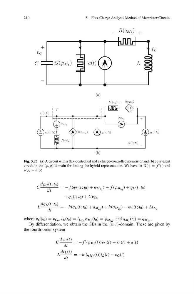
Fig. 5.25 (a) A circuit with a flux-controlled and a charge-controlled memristor and (b) equivalent
circuit in the (ϕ, q)-domain for finding the hybrid representation. We have let G(·) = f (·) and
R(·) = h (·)
C
dϕ C (t; t 0 )
dt
= −f (ϕ C (t; t 0 ) + ϕ M 1 0 ) + f (ϕ M 1 0 ) + q L (t; t 0 )
+q a (t; t 0 ) + Cv C 0
L
dq L (t; t 0 )
dt
= −h(q L (t; t 0 ) + q M 2 0 ) + h(q M 2 0 ) − ϕ C (t; t 0 ) + Li L 0
where v C (t 0 ) = v C 0 , i L (t 0 ) = i L 0 , ϕ M 1 (t 0 ) = ϕ M 1 0 , and q M 2 (t 0 ) = q M 2 0 .
By differentiation, we obtain the SEs in the (v, i)-domain. These are given by
the fourth-order system
C
dv C (t)
dt
= −f
(ϕ M 1 (t))v C (t) + i L (t) + a(t)
L
di L (t)
dt
= −h
(q M 2 (t))i L (t) − v C (t)
5 Flux-Charge Analysis Method of Memristor Circuits
C
G(ϕ M 1 )
a(t)
R(q M 2 )
L
i L
−
+
−
+
v C
Fig. 5.25 (a) A circuit with a flux-controlled and a charge-controlled memristor and (b) equivalent
circuit in the (ϕ, q)-domain for finding the hybrid representation. We have let G(·) = f (·) and
R(·) = h (·)
C
dϕ C (t; t 0 )
dt
= −f (ϕ C (t; t 0 ) + ϕ M 1 0 ) + f (ϕ M 1 0 ) + q L (t; t 0 )
+q a (t; t 0 ) + Cv C 0
L
dq L (t; t 0 )
dt
= −h(q L (t; t 0 ) + q M 2 0 ) + h(q M 2 0 ) − ϕ C (t; t 0 ) + Li L 0
where v C (t 0 ) = v C 0 , i L (t 0 ) = i L 0 , ϕ M 1 (t 0 ) = ϕ M 1 0 , and q M 2 (t 0 ) = q M 2 0 .
By differentiation, we obtain the SEs in the (v, i)-domain. These are given by
the fourth-order system
C
dv C (t)
dt
= −f
(ϕ M 1 (t))v C (t) + i L (t) + a(t)
L
di L (t)
dt
= −h
(q M 2 (t))i L (t) − v C (t)