

172
5 Flux-Charge Analysis Method of Memristor Circuits
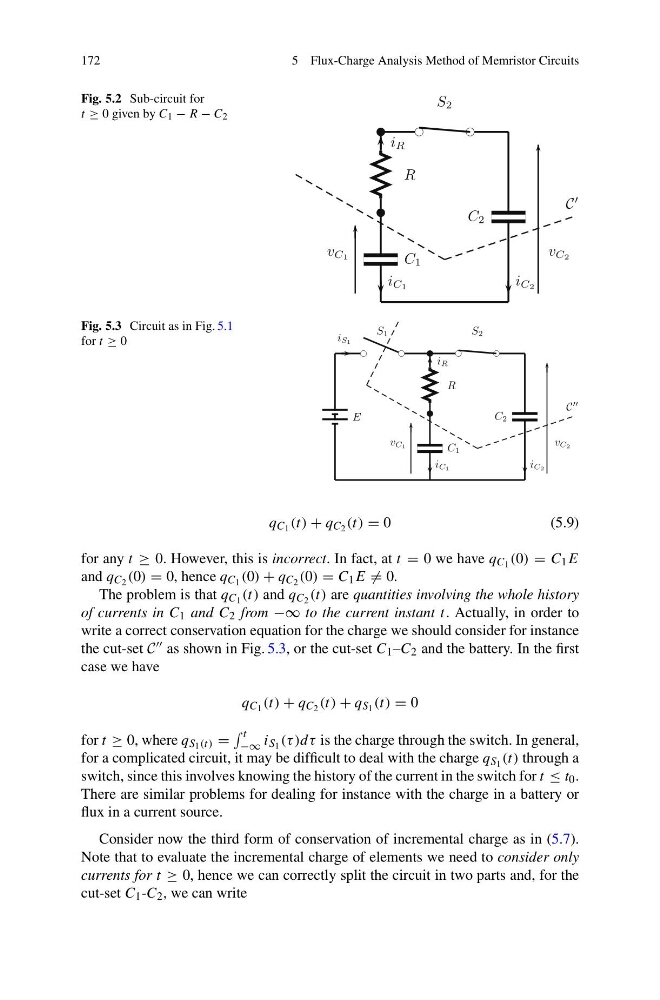
Fig. 5.2 Sub-circuit for
t ≥ 0 given by C 1 − R − C 2
R
C 1
S 2
C 2
v C1
i C1
i C2
i R
v C2
C
Fig. 5.3 Circuit as in Fig. 5.1
for t ≥ 0
E
S 1
R
C 1
S 2
C 2
v C1
i C1
i C2
i R
i S1
v C2
C
q C 1 (t) + q C 2 (t) = 0
(5.9)
for any t ≥ 0. However, this is incorrect. In fact, at t = 0 we have q C 1 (0) = C 1 E
and q C 2 (0) = 0, hence q C 1 (0) + q C 2 (0) = C 1 E = 0.
The problem is that q C 1 (t) and q C 2 (t) are quantities involving the whole history
of currents in C 1 and C 2 from −∞ to the current instant t. Actually, in order to
write a correct conservation equation for the charge we should consider for instance
the cut-set C as shown in Fig. 5.3, or the cut-set C 1 –C 2 and the battery. In the first
case we have
q C 1 (t) + q C 2 (t) + q S 1 (t) = 0
for t ≥ 0, where q S 1 (t) =
t
−∞ i S 1 (τ )dτ is the charge through the switch. In general,
for a complicated circuit, it may be difficult to deal with the charge q S 1 (t) through a
switch, since this involves knowing the history of the current in the switch for t ≤ t 0 .
There are similar problems for dealing for instance with the charge in a battery or
flux in a current source.
Consider now the third form of conservation of incremental charge as in (5.7).
Note that to evaluate the incremental charge of elements we need to consider only
currents for t ≥ 0, hence we can correctly split the circuit in two parts and, for the
cut-set C 1 -C 2 , we can write
5 Flux-Charge Analysis Method of Memristor Circuits
Fig. 5.2 Sub-circuit for
t ≥ 0 given by C 1 − R − C 2
R
C 1
S 2
C 2
v C1
i C1
i C2
i R
v C2
C
Fig. 5.3 Circuit as in Fig. 5.1
for t ≥ 0
E
S 1
R
C 1
S 2
C 2
v C1
i C1
i C2
i R
i S1
v C2
C
q C 1 (t) + q C 2 (t) = 0
(5.9)
for any t ≥ 0. However, this is incorrect. In fact, at t = 0 we have q C 1 (0) = C 1 E
and q C 2 (0) = 0, hence q C 1 (0) + q C 2 (0) = C 1 E = 0.
The problem is that q C 1 (t) and q C 2 (t) are quantities involving the whole history
of currents in C 1 and C 2 from −∞ to the current instant t. Actually, in order to
write a correct conservation equation for the charge we should consider for instance
the cut-set C as shown in Fig. 5.3, or the cut-set C 1 –C 2 and the battery. In the first
case we have
q C 1 (t) + q C 2 (t) + q S 1 (t) = 0
for t ≥ 0, where q S 1 (t) =
t
−∞ i S 1 (τ )dτ is the charge through the switch. In general,
for a complicated circuit, it may be difficult to deal with the charge q S 1 (t) through a
switch, since this involves knowing the history of the current in the switch for t ≤ t 0 .
There are similar problems for dealing for instance with the charge in a battery or
flux in a current source.
Consider now the third form of conservation of incremental charge as in (5.7).
Note that to evaluate the incremental charge of elements we need to consider only
currents for t ≥ 0, hence we can correctly split the circuit in two parts and, for the
cut-set C 1 -C 2 , we can write