

146
4 Nonlinear Dynamics and Bifurcations in Autonomous RLC Circuits
Fig. 4.13 Circuit with
inductor, tunnel diode, and
parasitic capacitance inserted
for breaking impasse points
L
C p
+
−
v
i
+
−
v L
iL
+
−
v C
iC
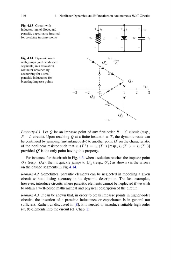
Fig. 4.14 Dynamic route
with jumps (vertical dashed
segments) in a relaxation
oscillator obtained by
accounting for a small
parasitic inductance for
breaking impasse points
Property 4.1 Let Q be an impasse point of any first-order R − C circuit (resp.,
R − L circuit). Upon reaching Q at a finite instant t = T , the dynamic route can
be continued by jumping (instantaneously) to another point Q on the characteristic
of the nonlinear resistor such that v C (T + ) = v C (T − ) [resp., i L (T + ) = i L (T − )]
provided Q is the only point having this property.
For instance, for the circuit in Fig. 4.3, when a solution reaches the impasse point
Q A (resp., Q B ), then it quickly jumps to Q
A (resp., Q
B ) as shown via the arrows
on the dashed segments in Fig. 4.14.
Remark 4.2 Sometimes, parasitic elements can be neglected in modeling a given
circuit without losing accuracy in its dynamic description. The last examples,
however, introduce circuits where parasitic elements cannot be neglected if we wish
to obtain a well-posed mathematical and physical description of the circuit.
Remark 4.3 It can be shown that, in order to break impasse points in higher-order
circuits, the insertion of a parasitic inductance or capacitance is in general not
sufficient. Rather, as discussed in [8], it is needed to introduce suitable high order
(α, β)-elements into the circuit (cf. Chap. 1).
4 Nonlinear Dynamics and Bifurcations in Autonomous RLC Circuits
Fig. 4.13 Circuit with
inductor, tunnel diode, and
parasitic capacitance inserted
for breaking impasse points
L
C p
+
−
v
i
+
−
v L
iL
+
−
v C
iC
Fig. 4.14 Dynamic route
with jumps (vertical dashed
segments) in a relaxation
oscillator obtained by
accounting for a small
parasitic inductance for
breaking impasse points
Property 4.1 Let Q be an impasse point of any first-order R − C circuit (resp.,
R − L circuit). Upon reaching Q at a finite instant t = T , the dynamic route can
be continued by jumping (instantaneously) to another point Q on the characteristic
of the nonlinear resistor such that v C (T + ) = v C (T − ) [resp., i L (T + ) = i L (T − )]
provided Q is the only point having this property.
For instance, for the circuit in Fig. 4.3, when a solution reaches the impasse point
Q A (resp., Q B ), then it quickly jumps to Q
A (resp., Q
B ) as shown via the arrows
on the dashed segments in Fig. 4.14.
Remark 4.2 Sometimes, parasitic elements can be neglected in modeling a given
circuit without losing accuracy in its dynamic description. The last examples,
however, introduce circuits where parasitic elements cannot be neglected if we wish
to obtain a well-posed mathematical and physical description of the circuit.
Remark 4.3 It can be shown that, in order to break impasse points in higher-order
circuits, the insertion of a parasitic inductance or capacitance is in general not
sufficient. Rather, as discussed in [8], it is needed to introduce suitable high order
(α, β)-elements into the circuit (cf. Chap. 1).