

4.1 First-Order Circuits
135
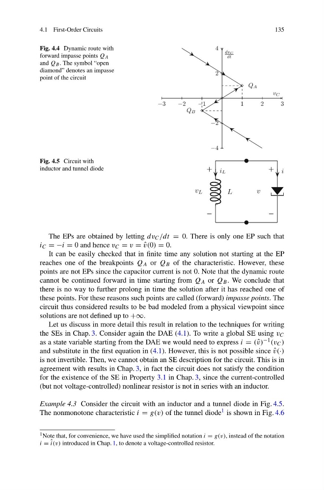
Fig. 4.4 Dynamic route with
forward impasse points Q A
and Q B . The symbol “open
diamond” denotes an impasse
point of the circuit
Fig. 4.5 Circuit with
inductor and tunnel diode
The EPs are obtained by letting dv C /dt = 0. There is only one EP such that
i C = −i = 0 and hence v C = v = ˆ
v(0) = 0.
It can be easily checked that in finite time any solution not starting at the EP
reaches one of the breakpoints Q A or Q B of the characteristic. However, these
points are not EPs since the capacitor current is not 0. Note that the dynamic route
cannot be continued forward in time starting from Q A or Q B . We conclude that
there is no way to further prolong in time the solution after it has reached one of
these points. For these reasons such points are called (forward) impasse points. The
circuit thus considered results to be bad modeled from a physical viewpoint since
solutions are not defined up to +∞.
Let us discuss in more detail this result in relation to the techniques for writing
the SEs in Chap. 3. Consider again the DAE (4.1). To write a global SE using v C
as a state variable starting from the DAE we would need to express i = ( ˆ
v) −1 (v C )
and substitute in the first equation in (4.1). However, this is not possible since ˆ
v(·)
is not invertible. Then, we cannot obtain an SE description for the circuit. This is in
agreement with results in Chap. 3, in fact the circuit does not satisfy the condition
for the existence of the SE in Property 3.1 in Chap. 3, since the current-controlled
(but not voltage-controlled) nonlinear resistor is not in series with an inductor.
Example 4.3 Consider the circuit with an inductor and a tunnel diode in Fig. 4.5.
The nonmonotone characteristic i = g(v) of the tunnel diode 1 is shown in Fig. 4.6
1 Note that, for convenience, we have used the simplified notation i = g(v), instead of the notation
i = ˆ
i(v) introduced in Chap. 1, to denote a voltage-controlled resistor.
135
Fig. 4.4 Dynamic route with
forward impasse points Q A
and Q B . The symbol “open
diamond” denotes an impasse
point of the circuit
Fig. 4.5 Circuit with
inductor and tunnel diode
The EPs are obtained by letting dv C /dt = 0. There is only one EP such that
i C = −i = 0 and hence v C = v = ˆ
v(0) = 0.
It can be easily checked that in finite time any solution not starting at the EP
reaches one of the breakpoints Q A or Q B of the characteristic. However, these
points are not EPs since the capacitor current is not 0. Note that the dynamic route
cannot be continued forward in time starting from Q A or Q B . We conclude that
there is no way to further prolong in time the solution after it has reached one of
these points. For these reasons such points are called (forward) impasse points. The
circuit thus considered results to be bad modeled from a physical viewpoint since
solutions are not defined up to +∞.
Let us discuss in more detail this result in relation to the techniques for writing
the SEs in Chap. 3. Consider again the DAE (4.1). To write a global SE using v C
as a state variable starting from the DAE we would need to express i = ( ˆ
v) −1 (v C )
and substitute in the first equation in (4.1). However, this is not possible since ˆ
v(·)
is not invertible. Then, we cannot obtain an SE description for the circuit. This is in
agreement with results in Chap. 3, in fact the circuit does not satisfy the condition
for the existence of the SE in Property 3.1 in Chap. 3, since the current-controlled
(but not voltage-controlled) nonlinear resistor is not in series with an inductor.
Example 4.3 Consider the circuit with an inductor and a tunnel diode in Fig. 4.5.
The nonmonotone characteristic i = g(v) of the tunnel diode 1 is shown in Fig. 4.6
1 Note that, for convenience, we have used the simplified notation i = g(v), instead of the notation
i = ˆ
i(v) introduced in Chap. 1, to denote a voltage-controlled resistor.