

126
3 RLC Networks Equations and Analysis Methods
C 1
i C1
+
−
v C1
+
−
v a1
i a1
•
•
•
•
L 1
i L1
−
+
v L1
+
−
v b1
i b1
•
•
•
•
e s (t)
i s (t)
N
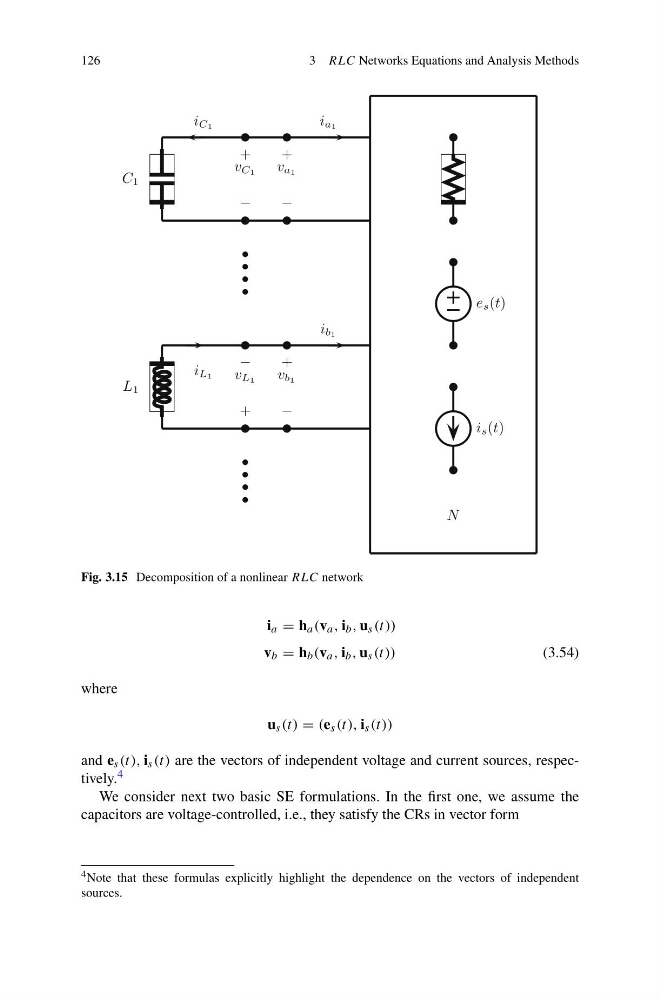
Fig. 3.15 Decomposition of a nonlinear RLC network
i a = h a (v a , i b , u s (t))
v b = h b (v a , i b , u s (t))
(3.54)
where
u s (t) = (e s (t), i s (t))
and e s (t), i s (t) are the vectors of independent voltage and current sources, respectively. 4
We consider next two basic SE formulations. In the first one, we assume the
capacitors are voltage-controlled, i.e., they satisfy the CRs in vector form
4 Note that these formulas explicitly highlight the dependence on the vectors of independent
sources.
3 RLC Networks Equations and Analysis Methods
C 1
i C1
+
−
v C1
+
−
v a1
i a1
•
•
•
•
L 1
i L1
−
+
v L1
+
−
v b1
i b1
•
•
•
•
e s (t)
i s (t)
N
Fig. 3.15 Decomposition of a nonlinear RLC network
i a = h a (v a , i b , u s (t))
v b = h b (v a , i b , u s (t))
(3.54)
where
u s (t) = (e s (t), i s (t))
and e s (t), i s (t) are the vectors of independent voltage and current sources, respectively. 4
We consider next two basic SE formulations. In the first one, we assume the
capacitors are voltage-controlled, i.e., they satisfy the CRs in vector form
4 Note that these formulas explicitly highlight the dependence on the vectors of independent
sources.