

3.3 State Equations
125
C 1
1 Ω
cos(2t)
1 Ω
1 Ω
L 2
+
−
v 1
i1
+
−
v C1
iC 1
+
−
v 2
i2
−
+
v L2
iL 2
(a)
v 1
1 Ω
cos(2t)
1 Ω
1 Ω
i 2
+
−
v 1
i1
+
−
v 2
i2
(b)
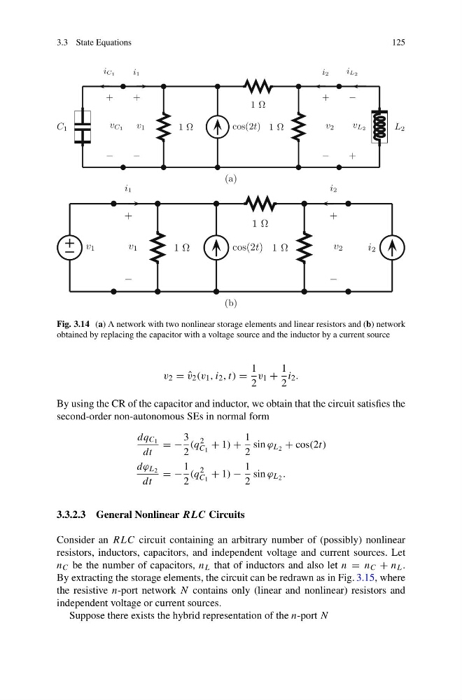
Fig. 3.14 (a) A network with two nonlinear storage elements and linear resistors and (b) network
obtained by replacing the capacitor with a voltage source and the inductor by a current source
v 2 = ˆ
v 2 (v 1 , i 2 , t) =
1
2
v 1 +
1
2
i 2 .
By using the CR of the capacitor and inductor, we obtain that the circuit satisfies the
second-order non-autonomous SEs in normal form
dq C 1
dt
= −
3
2
(q
2
C 1
+ 1) +
1
2
sin ϕ L 2 + cos(2t)
dϕ L 2
dt
= −
1
2
(q
2
C 1
+ 1) −
1
2
sin ϕ L 2 .
3.3.2.3 General Nonlinear RLC Circuits
Consider an RLC circuit containing an arbitrary number of (possibly) nonlinear
resistors, inductors, capacitors, and independent voltage and current sources. Let
n C be the number of capacitors, n L that of inductors and also let n = n C + n L .
By extracting the storage elements, the circuit can be redrawn as in Fig. 3.15, where
the resistive n-port network N contains only (linear and nonlinear) resistors and
independent voltage or current sources.
Suppose there exists the hybrid representation of the n-port N
125
C 1
1 Ω
cos(2t)
1 Ω
1 Ω
L 2
+
−
v 1
i1
+
−
v C1
iC 1
+
−
v 2
i2
−
+
v L2
iL 2
(a)
v 1
1 Ω
cos(2t)
1 Ω
1 Ω
i 2
+
−
v 1
i1
+
−
v 2
i2
(b)
Fig. 3.14 (a) A network with two nonlinear storage elements and linear resistors and (b) network
obtained by replacing the capacitor with a voltage source and the inductor by a current source
v 2 = ˆ
v 2 (v 1 , i 2 , t) =
1
2
v 1 +
1
2
i 2 .
By using the CR of the capacitor and inductor, we obtain that the circuit satisfies the
second-order non-autonomous SEs in normal form
dq C 1
dt
= −
3
2
(q
2
C 1
+ 1) +
1
2
sin ϕ L 2 + cos(2t)
dϕ L 2
dt
= −
1
2
(q
2
C 1
+ 1) −
1
2
sin ϕ L 2 .
3.3.2.3 General Nonlinear RLC Circuits
Consider an RLC circuit containing an arbitrary number of (possibly) nonlinear
resistors, inductors, capacitors, and independent voltage and current sources. Let
n C be the number of capacitors, n L that of inductors and also let n = n C + n L .
By extracting the storage elements, the circuit can be redrawn as in Fig. 3.15, where
the resistive n-port network N contains only (linear and nonlinear) resistors and
independent voltage or current sources.
Suppose there exists the hybrid representation of the n-port N