

3.3 Surface Effects
49
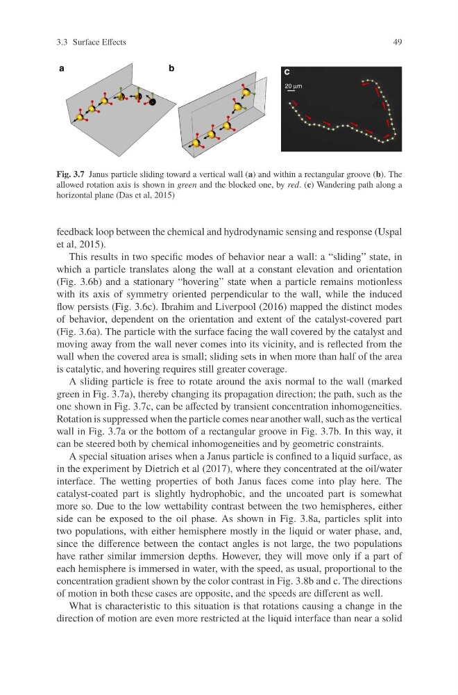
Fig. 3.7 Janus particle sliding toward a vertical wall (a) and within a rectangular groove (b). The
allowed rotation axis is shown in green and the blocked one, by red. (c) Wandering path along a
horizontal plane (Das et al, 2015)
feedback loop between the chemical and hydrodynamic sensing and response (Uspal
et al, 2015).
This results in two specific modes of behavior near a wall: a “sliding” state, in
which a particle translates along the wall at a constant elevation and orientation
(Fig. 3.6b) and a stationary “hovering” state when a particle remains motionless
with its axis of symmetry oriented perpendicular to the wall, while the induced
flow persists (Fig. 3.6c). Ibrahim and Liverpool (2016) mapped the distinct modes
of behavior, dependent on the orientation and extent of the catalyst-covered part
(Fig. 3.6a). The particle with the surface facing the wall covered by the catalyst and
moving away from the wall never comes into its vicinity, and is reflected from the
wall when the covered area is small; sliding sets in when more than half of the area
is catalytic, and hovering requires still greater coverage.
A sliding particle is free to rotate around the axis normal to the wall (marked
green in Fig. 3.7a), thereby changing its propagation direction; the path, such as the
one shown in Fig. 3.7c, can be affected by transient concentration inhomogeneities.
Rotation is suppressed when the particle comes near another wall, such as the vertical
wall in Fig. 3.7a or the bottom of a rectangular groove in Fig. 3.7b. In this way, it
can be steered both by chemical inhomogeneities and by geometric constraints.
A special situation arises when a Janus particle is confined to a liquid surface, as
in the experiment by Dietrich et al (2017), where they concentrated at the oil/water
interface. The wetting properties of both Janus faces come into play here. The
catalyst-coated part is slightly hydrophobic, and the uncoated part is somewhat
more so. Due to the low wettability contrast between the two hemispheres, either
side can be exposed to the oil phase. As shown in Fig. 3.8a, particles split into
two populations, with either hemisphere mostly in the liquid or water phase, and,
since the difference between the contact angles is not large, the two populations
have rather similar immersion depths. However, they will move only if a part of
each hemisphere is immersed in water, with the speed, as usual, proportional to the
concentration gradient shown by the color contrast in Fig. 3.8b and c. The directions
of motion in both these cases are opposite, and the speeds are different as well.
What is characteristic to this situation is that rotations causing a change in the
direction of motion are even more restricted at the liquid interface than near a solid
49
Fig. 3.7 Janus particle sliding toward a vertical wall (a) and within a rectangular groove (b). The
allowed rotation axis is shown in green and the blocked one, by red. (c) Wandering path along a
horizontal plane (Das et al, 2015)
feedback loop between the chemical and hydrodynamic sensing and response (Uspal
et al, 2015).
This results in two specific modes of behavior near a wall: a “sliding” state, in
which a particle translates along the wall at a constant elevation and orientation
(Fig. 3.6b) and a stationary “hovering” state when a particle remains motionless
with its axis of symmetry oriented perpendicular to the wall, while the induced
flow persists (Fig. 3.6c). Ibrahim and Liverpool (2016) mapped the distinct modes
of behavior, dependent on the orientation and extent of the catalyst-covered part
(Fig. 3.6a). The particle with the surface facing the wall covered by the catalyst and
moving away from the wall never comes into its vicinity, and is reflected from the
wall when the covered area is small; sliding sets in when more than half of the area
is catalytic, and hovering requires still greater coverage.
A sliding particle is free to rotate around the axis normal to the wall (marked
green in Fig. 3.7a), thereby changing its propagation direction; the path, such as the
one shown in Fig. 3.7c, can be affected by transient concentration inhomogeneities.
Rotation is suppressed when the particle comes near another wall, such as the vertical
wall in Fig. 3.7a or the bottom of a rectangular groove in Fig. 3.7b. In this way, it
can be steered both by chemical inhomogeneities and by geometric constraints.
A special situation arises when a Janus particle is confined to a liquid surface, as
in the experiment by Dietrich et al (2017), where they concentrated at the oil/water
interface. The wetting properties of both Janus faces come into play here. The
catalyst-coated part is slightly hydrophobic, and the uncoated part is somewhat
more so. Due to the low wettability contrast between the two hemispheres, either
side can be exposed to the oil phase. As shown in Fig. 3.8a, particles split into
two populations, with either hemisphere mostly in the liquid or water phase, and,
since the difference between the contact angles is not large, the two populations
have rather similar immersion depths. However, they will move only if a part of
each hemisphere is immersed in water, with the speed, as usual, proportional to the
concentration gradient shown by the color contrast in Fig. 3.8b and c. The directions
of motion in both these cases are opposite, and the speeds are different as well.
What is characteristic to this situation is that rotations causing a change in the
direction of motion are even more restricted at the liquid interface than near a solid