

course is at the base also of the optical diffraction pattern, but it does not explain
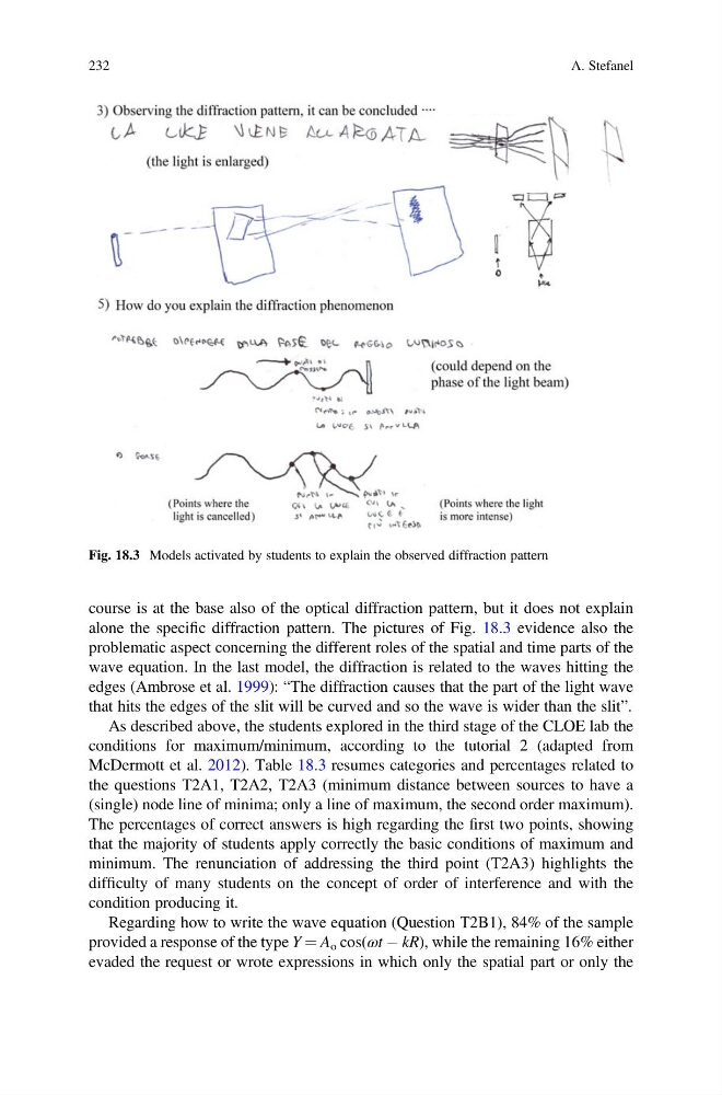
alone the specific diffraction pattern. The pictures of Fig. 18.3 evidence also the
problematic aspect concerning the different roles of the spatial and time parts of the
wave equation. In the last model, the diffraction is related to the waves hitting the
edges (Ambrose et al. 1999): “The diffraction causes that the part of the light wave
that hits the edges of the slit will be curved and so the wave is wider than the slit”.
As described above, the students explored in the third stage of the CLOE lab the
conditions for maximum/minimum, according to the tutorial 2 (adapted from
McDermott et al. 2012). Table 18.3 resumes categories and percentages related to
the questions T2A1, T2A2, T2A3 (minimum distance between sources to have a
(single) node line of minima; only a line of maximum, the second order maximum).
The percentages of correct answers is high regarding the first two points, showing
that the majority of students apply correctly the basic conditions of maximum and
minimum. The renunciation of addressing the third point (T2A3) highlights the
difficulty of many students on the concept of order of interference and with the
condition producing it.
Regarding how to write the wave equation (Question T2B1), 84% of the sample
provided a response of the type Y ¼ A o cos(ωt À kR), while the remaining 16% either
evaded the request or wrote expressions in which only the spatial part or only the
Fig. 18.3 Models activated by students to explain the observed diffraction pattern
232
A. Stefanel
alone the specific diffraction pattern. The pictures of Fig. 18.3 evidence also the
problematic aspect concerning the different roles of the spatial and time parts of the
wave equation. In the last model, the diffraction is related to the waves hitting the
edges (Ambrose et al. 1999): “The diffraction causes that the part of the light wave
that hits the edges of the slit will be curved and so the wave is wider than the slit”.
As described above, the students explored in the third stage of the CLOE lab the
conditions for maximum/minimum, according to the tutorial 2 (adapted from
McDermott et al. 2012). Table 18.3 resumes categories and percentages related to
the questions T2A1, T2A2, T2A3 (minimum distance between sources to have a
(single) node line of minima; only a line of maximum, the second order maximum).
The percentages of correct answers is high regarding the first two points, showing
that the majority of students apply correctly the basic conditions of maximum and
minimum. The renunciation of addressing the third point (T2A3) highlights the
difficulty of many students on the concept of order of interference and with the
condition producing it.
Regarding how to write the wave equation (Question T2B1), 84% of the sample
provided a response of the type Y ¼ A o cos(ωt À kR), while the remaining 16% either
evaded the request or wrote expressions in which only the spatial part or only the
Fig. 18.3 Models activated by students to explain the observed diffraction pattern
232
A. Stefanel