

5.2 Crossing the Threshold: Small Amplitude Oscillating Solutions
225
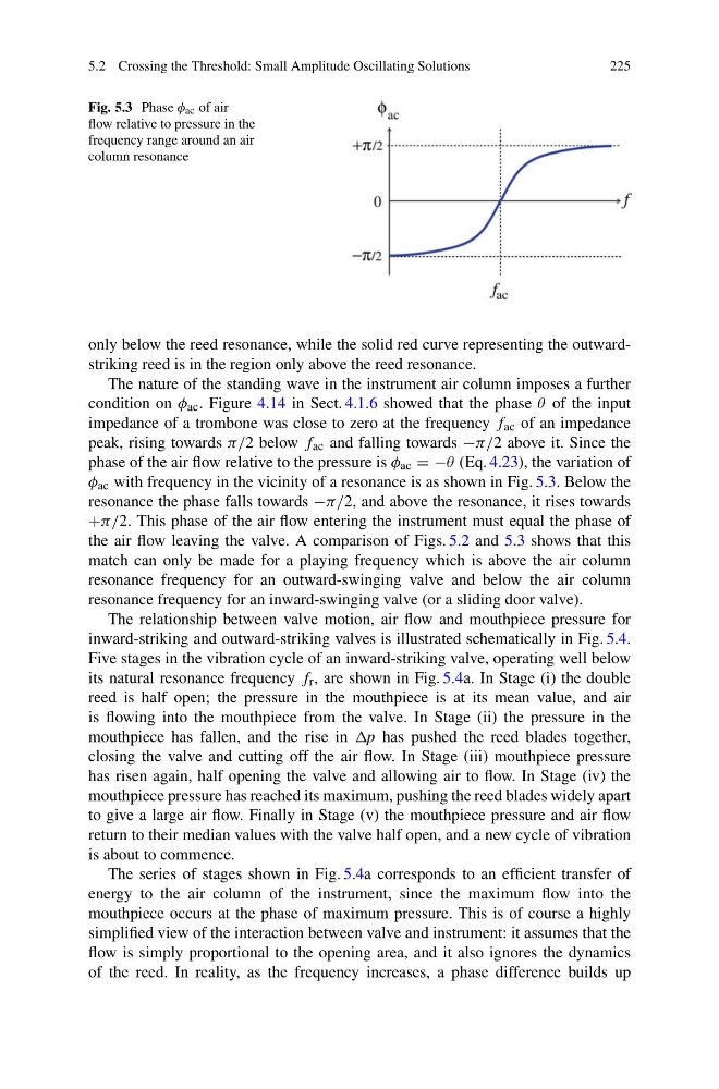
Fig. 5.3 Phase φ ac of air
flow relative to pressure in the
frequency range around an air
column resonance
only below the reed resonance, while the solid red curve representing the outwardstriking reed is in the region only above the reed resonance.
The nature of the standing wave in the instrument air column imposes a further
condition on φ ac . Figure 4.14 in Sect. 4.1.6 showed that the phase θ of the input
impedance of a trombone was close to zero at the frequency f ac of an impedance
peak, rising towards π/2 below f ac and falling towards −π/2 above it. Since the
phase of the air flow relative to the pressure is φ ac = −θ (Eq. 4.23), the variation of
φ ac with frequency in the vicinity of a resonance is as shown in Fig. 5.3. Below the
resonance the phase falls towards −π/2, and above the resonance, it rises towards
+π/2. This phase of the air flow entering the instrument must equal the phase of
the air flow leaving the valve. A comparison of Figs. 5.2 and 5.3 shows that this
match can only be made for a playing frequency which is above the air column
resonance frequency for an outward-swinging valve and below the air column
resonance frequency for an inward-swinging valve (or a sliding door valve).
The relationship between valve motion, air flow and mouthpiece pressure for
inward-striking and outward-striking valves is illustrated schematically in Fig. 5.4.
Five stages in the vibration cycle of an inward-striking valve, operating well below
its natural resonance frequency f r , are shown in Fig. 5.4a. In Stage (i) the double
reed is half open; the pressure in the mouthpiece is at its mean value, and air
is flowing into the mouthpiece from the valve. In Stage (ii) the pressure in the
mouthpiece has fallen, and the rise in p has pushed the reed blades together,
closing the valve and cutting off the air flow. In Stage (iii) mouthpiece pressure
has risen again, half opening the valve and allowing air to flow. In Stage (iv) the
mouthpiece pressure has reached its maximum, pushing the reed blades widely apart
to give a large air flow. Finally in Stage (v) the mouthpiece pressure and air flow
return to their median values with the valve half open, and a new cycle of vibration
is about to commence.
The series of stages shown in Fig. 5.4a corresponds to an efficient transfer of
energy to the air column of the instrument, since the maximum flow into the
mouthpiece occurs at the phase of maximum pressure. This is of course a highly
simplified view of the interaction between valve and instrument: it assumes that the
flow is simply proportional to the opening area, and it also ignores the dynamics
of the reed. In reality, as the frequency increases, a phase difference builds up
225
Fig. 5.3 Phase φ ac of air
flow relative to pressure in the
frequency range around an air
column resonance
only below the reed resonance, while the solid red curve representing the outwardstriking reed is in the region only above the reed resonance.
The nature of the standing wave in the instrument air column imposes a further
condition on φ ac . Figure 4.14 in Sect. 4.1.6 showed that the phase θ of the input
impedance of a trombone was close to zero at the frequency f ac of an impedance
peak, rising towards π/2 below f ac and falling towards −π/2 above it. Since the
phase of the air flow relative to the pressure is φ ac = −θ (Eq. 4.23), the variation of
φ ac with frequency in the vicinity of a resonance is as shown in Fig. 5.3. Below the
resonance the phase falls towards −π/2, and above the resonance, it rises towards
+π/2. This phase of the air flow entering the instrument must equal the phase of
the air flow leaving the valve. A comparison of Figs. 5.2 and 5.3 shows that this
match can only be made for a playing frequency which is above the air column
resonance frequency for an outward-swinging valve and below the air column
resonance frequency for an inward-swinging valve (or a sliding door valve).
The relationship between valve motion, air flow and mouthpiece pressure for
inward-striking and outward-striking valves is illustrated schematically in Fig. 5.4.
Five stages in the vibration cycle of an inward-striking valve, operating well below
its natural resonance frequency f r , are shown in Fig. 5.4a. In Stage (i) the double
reed is half open; the pressure in the mouthpiece is at its mean value, and air
is flowing into the mouthpiece from the valve. In Stage (ii) the pressure in the
mouthpiece has fallen, and the rise in p has pushed the reed blades together,
closing the valve and cutting off the air flow. In Stage (iii) mouthpiece pressure
has risen again, half opening the valve and allowing air to flow. In Stage (iv) the
mouthpiece pressure has reached its maximum, pushing the reed blades widely apart
to give a large air flow. Finally in Stage (v) the mouthpiece pressure and air flow
return to their median values with the valve half open, and a new cycle of vibration
is about to commence.
The series of stages shown in Fig. 5.4a corresponds to an efficient transfer of
energy to the air column of the instrument, since the maximum flow into the
mouthpiece occurs at the phase of maximum pressure. This is of course a highly
simplified view of the interaction between valve and instrument: it assumes that the
flow is simply proportional to the opening area, and it also ignores the dynamics
of the reed. In reality, as the frequency increases, a phase difference builds up