

224
5 Blow That Horn: An Elementary Model of Brass Playing
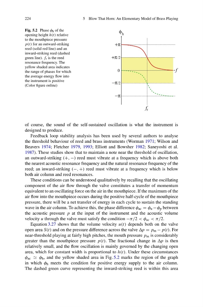
Fig. 5.2 Phase φ h of the
opening height h(t) relative
to the mouthpiece pressure
p(t) for an outward-striking
reed (solid red line) and an
inward-striking reed (dashed
green line). f r is the reed
resonance frequency. The
yellow shaded area indicates
the range of phases for which
the average energy flow into
the instrument is positive
(Color figure online)
−π
+π
−π/2
/2
+π
f r
φ h
f
0
of course, the sound of the self-sustained oscillation is what the instrument is
designed to produce.
Feedback loop stability analysis has been used by several authors to analyse
the threshold behaviour of reed and brass instruments (Worman 1971; Wilson and
Beavers 1974; Fletcher 1979, 1993; Elliott and Bowsher 1982; Saneyoshi et al.
1987). These studies show that to maintain a note near the threshold of oscillation,
an outward-striking (+, −) reed must vibrate at a frequency which is above both
the nearest acoustic resonance frequency and the natural resonance frequency of the
reed; an inward-striking (−, +) reed must vibrate at a frequency which is below
both air column and reed resonances.
These conditions can be understood qualitatively by recalling that the oscillating
component of the air flow through the valve constitutes a transfer of momentum
equivalent to an oscillating force on the air in the mouthpiece. If the maximum of the
air flow into the mouthpiece occurs during the positive half-cycle of the mouthpiece
pressure, there will be a net transfer of energy in each cycle to sustain the standing
wave in the air column. To achieve this, the phase difference φ ac = φ u − φ p between
the acoustic pressure p at the input of the instrument and the acoustic volume
velocity u through the valve must satisfy the condition −π/2 < φ ac < π/2.
Equation 3.27 shows that the volume velocity u(t) depends both on the valve
open area S(t) and on the pressure difference across the valve p = p m − p(t). For
near-threshold playing at fairly high pitches, the mouth pressure p m is considerably
greater than the mouthpiece pressure p(t). The fractional change in p is then
relatively small, and the flow oscillation is mainly governed by the changing open
area, which for constant width is proportional to h(t). Under these circumstances
φ ac φ h , and the yellow shaded area in Fig. 5.2 marks the region of the graph
in which φ h meets the condition for positive energy supply to the air column.
The dashed green curve representing the inward-striking reed is within this area
5 Blow That Horn: An Elementary Model of Brass Playing
Fig. 5.2 Phase φ h of the
opening height h(t) relative
to the mouthpiece pressure
p(t) for an outward-striking
reed (solid red line) and an
inward-striking reed (dashed
green line). f r is the reed
resonance frequency. The
yellow shaded area indicates
the range of phases for which
the average energy flow into
the instrument is positive
(Color figure online)
−π
+π
−π/2
/2
+π
f r
φ h
f
0
of course, the sound of the self-sustained oscillation is what the instrument is
designed to produce.
Feedback loop stability analysis has been used by several authors to analyse
the threshold behaviour of reed and brass instruments (Worman 1971; Wilson and
Beavers 1974; Fletcher 1979, 1993; Elliott and Bowsher 1982; Saneyoshi et al.
1987). These studies show that to maintain a note near the threshold of oscillation,
an outward-striking (+, −) reed must vibrate at a frequency which is above both
the nearest acoustic resonance frequency and the natural resonance frequency of the
reed; an inward-striking (−, +) reed must vibrate at a frequency which is below
both air column and reed resonances.
These conditions can be understood qualitatively by recalling that the oscillating
component of the air flow through the valve constitutes a transfer of momentum
equivalent to an oscillating force on the air in the mouthpiece. If the maximum of the
air flow into the mouthpiece occurs during the positive half-cycle of the mouthpiece
pressure, there will be a net transfer of energy in each cycle to sustain the standing
wave in the air column. To achieve this, the phase difference φ ac = φ u − φ p between
the acoustic pressure p at the input of the instrument and the acoustic volume
velocity u through the valve must satisfy the condition −π/2 < φ ac < π/2.
Equation 3.27 shows that the volume velocity u(t) depends both on the valve
open area S(t) and on the pressure difference across the valve p = p m − p(t). For
near-threshold playing at fairly high pitches, the mouth pressure p m is considerably
greater than the mouthpiece pressure p(t). The fractional change in p is then
relatively small, and the flow oscillation is mainly governed by the changing open
area, which for constant width is proportional to h(t). Under these circumstances
φ ac φ h , and the yellow shaded area in Fig. 5.2 marks the region of the graph
in which φ h meets the condition for positive energy supply to the air column.
The dashed green curve representing the inward-striking reed is within this area