

96
3 Buzzing Lips: Sound Generation in Brass Instruments
3.5 Volume Flow in Buzzing Lips
The mechanical behaviour of a relatively simple lip model based on a 1DOF
mechanical oscillator has been described in Sect. 3.2 and compared with experimental measurements in Sect. 3.3. In Sect. 3.5 we consider the hydrodynamic behaviour
of the air which flows from the mouth through the channel between the two lips into
the mouthpiece and derive an equation relating the volume flow through the lips
to the pressure difference across them. This equation forms the second important
constituent of the model of brass playing which is developed in Chap. 5.
3.5.1 Acoustic Volume Flow Through the Lip Aperture
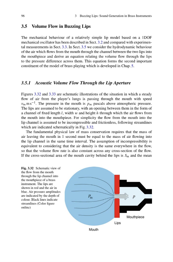
Figures 3.32 and 3.33 are schematic illustrations of the situation in which a steady
flow of air from the player’s lungs is passing through the mouth with speed
v m m s −1 . The pressure in the mouth is p m pascals above atmospheric pressure.
The lips are assumed to be stationary, with an opening between them in the form of
a channel of fixed length l, width w and height h through which the air flows from
the mouth into the mouthpiece. For simplicity the flow from the mouth into the
lip channel is assumed to be incompressible and frictionless, following streamlines
which are indicated schematically in Fig. 3.32.
The fundamental physical law of mass conservation requires that the mass of
air leaving the mouth in 1 second must be equal to the mass of air flowing into
the lip channel in the same time interval. The assumption of incompressibility is
equivalent to considering that the air density is the same everywhere in the flow,
so that the volume flow rate is also constant across any cross-section of the flow.
If the cross-sectional area of the mouth cavity behind the lips is S m and the mean
Fig. 3.32 Schematic view of
the flow from the mouth
through the lip channel into
the mouthpiece of a brass
instrument. The lips are
shown in red and the air in
blue. Air pressure amplitudes
are indicated by the depth of
colour. Black lines indicate
streamlines (Color figure
online)
3 Buzzing Lips: Sound Generation in Brass Instruments
3.5 Volume Flow in Buzzing Lips
The mechanical behaviour of a relatively simple lip model based on a 1DOF
mechanical oscillator has been described in Sect. 3.2 and compared with experimental measurements in Sect. 3.3. In Sect. 3.5 we consider the hydrodynamic behaviour
of the air which flows from the mouth through the channel between the two lips into
the mouthpiece and derive an equation relating the volume flow through the lips
to the pressure difference across them. This equation forms the second important
constituent of the model of brass playing which is developed in Chap. 5.
3.5.1 Acoustic Volume Flow Through the Lip Aperture
Figures 3.32 and 3.33 are schematic illustrations of the situation in which a steady
flow of air from the player’s lungs is passing through the mouth with speed
v m m s −1 . The pressure in the mouth is p m pascals above atmospheric pressure.
The lips are assumed to be stationary, with an opening between them in the form of
a channel of fixed length l, width w and height h through which the air flows from
the mouth into the mouthpiece. For simplicity the flow from the mouth into the
lip channel is assumed to be incompressible and frictionless, following streamlines
which are indicated schematically in Fig. 3.32.
The fundamental physical law of mass conservation requires that the mass of
air leaving the mouth in 1 second must be equal to the mass of air flowing into
the lip channel in the same time interval. The assumption of incompressibility is
equivalent to considering that the air density is the same everywhere in the flow,
so that the volume flow rate is also constant across any cross-section of the flow.
If the cross-sectional area of the mouth cavity behind the lips is S m and the mean
Fig. 3.32 Schematic view of
the flow from the mouth
through the lip channel into
the mouthpiece of a brass
instrument. The lips are
shown in red and the air in
blue. Air pressure amplitudes
are indicated by the depth of
colour. Black lines indicate
streamlines (Color figure
online)