

3.3 The Mechanical Response of the Vibrating Lips
91
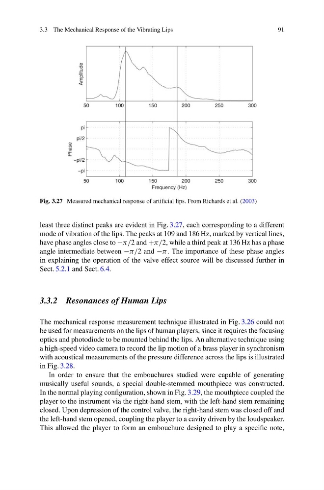
Fig. 3.27 Measured mechanical response of artificial lips. From Richards et al. (2003)
least three distinct peaks are evident in Fig. 3.27, each corresponding to a different
mode of vibration of the lips. The peaks at 109 and 186 Hz, marked by vertical lines,
have phase angles close to −π/2 and +π/2, while a third peak at 136 Hz has a phase
angle intermediate between −π/2 and −π . The importance of these phase angles
in explaining the operation of the valve effect source will be discussed further in
Sect. 5.2.1 and Sect. 6.4.
3.3.2 Resonances of Human Lips
The mechanical response measurement technique illustrated in Fig. 3.26 could not
be used for measurements on the lips of human players, since it requires the focusing
optics and photodiode to be mounted behind the lips. An alternative technique using
a high-speed video camera to record the lip motion of a brass player in synchronism
with acoustical measurements of the pressure difference across the lips is illustrated
in Fig. 3.28.
In order to ensure that the embouchures studied were capable of generating
musically useful sounds, a special double-stemmed mouthpiece was constructed.
In the normal playing configuration, shown in Fig. 3.29, the mouthpiece coupled the
player to the instrument via the right-hand stem, with the left-hand stem remaining
closed. Upon depression of the control valve, the right-hand stem was closed off and
the left-hand stem opened, coupling the player to a cavity driven by the loudspeaker.
This allowed the player to form an embouchure designed to play a specific note,
91
Fig. 3.27 Measured mechanical response of artificial lips. From Richards et al. (2003)
least three distinct peaks are evident in Fig. 3.27, each corresponding to a different
mode of vibration of the lips. The peaks at 109 and 186 Hz, marked by vertical lines,
have phase angles close to −π/2 and +π/2, while a third peak at 136 Hz has a phase
angle intermediate between −π/2 and −π . The importance of these phase angles
in explaining the operation of the valve effect source will be discussed further in
Sect. 5.2.1 and Sect. 6.4.
3.3.2 Resonances of Human Lips
The mechanical response measurement technique illustrated in Fig. 3.26 could not
be used for measurements on the lips of human players, since it requires the focusing
optics and photodiode to be mounted behind the lips. An alternative technique using
a high-speed video camera to record the lip motion of a brass player in synchronism
with acoustical measurements of the pressure difference across the lips is illustrated
in Fig. 3.28.
In order to ensure that the embouchures studied were capable of generating
musically useful sounds, a special double-stemmed mouthpiece was constructed.
In the normal playing configuration, shown in Fig. 3.29, the mouthpiece coupled the
player to the instrument via the right-hand stem, with the left-hand stem remaining
closed. Upon depression of the control valve, the right-hand stem was closed off and
the left-hand stem opened, coupling the player to a cavity driven by the loudspeaker.
This allowed the player to form an embouchure designed to play a specific note,