

90
3 Buzzing Lips: Sound Generation in Brass Instruments
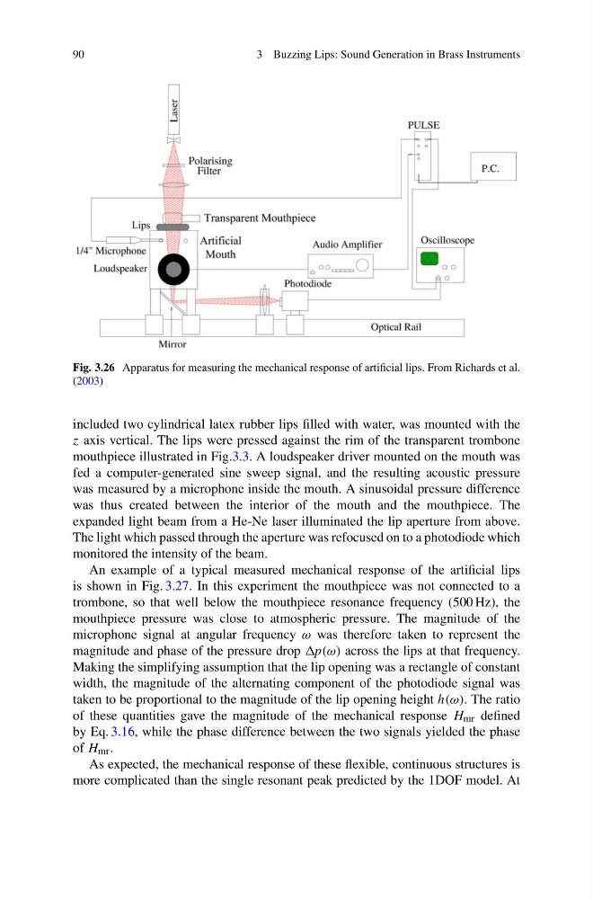
Fig. 3.26 Apparatus for measuring the mechanical response of artificial lips. From Richards et al.
(2003)
included two cylindrical latex rubber lips filled with water, was mounted with the
z axis vertical. The lips were pressed against the rim of the transparent trombone
mouthpiece illustrated in Fig.3.3. A loudspeaker driver mounted on the mouth was
fed a computer-generated sine sweep signal, and the resulting acoustic pressure
was measured by a microphone inside the mouth. A sinusoidal pressure difference
was thus created between the interior of the mouth and the mouthpiece. The
expanded light beam from a He-Ne laser illuminated the lip aperture from above.
The light which passed through the aperture was refocused on to a photodiode which
monitored the intensity of the beam.
An example of a typical measured mechanical response of the artificial lips
is shown in Fig. 3.27. In this experiment the mouthpiece was not connected to a
trombone, so that well below the mouthpiece resonance frequency (500 Hz), the
mouthpiece pressure was close to atmospheric pressure. The magnitude of the
microphone signal at angular frequency ω was therefore taken to represent the
magnitude and phase of the pressure drop across the lips at that frequency.
Making the simplifying assumption that the lip opening was a rectangle of constant
width, the magnitude of the alternating component of the photodiode signal was
taken to be proportional to the magnitude of the lip opening height h(ω). The ratio
of these quantities gave the magnitude of the mechanical response H mr defined
by Eq. 3.16, while the phase difference between the two signals yielded the phase
of H mr .
As expected, the mechanical response of these flexible, continuous structures is
more complicated than the single resonant peak predicted by the 1DOF model. At
3 Buzzing Lips: Sound Generation in Brass Instruments
Fig. 3.26 Apparatus for measuring the mechanical response of artificial lips. From Richards et al.
(2003)
included two cylindrical latex rubber lips filled with water, was mounted with the
z axis vertical. The lips were pressed against the rim of the transparent trombone
mouthpiece illustrated in Fig.3.3. A loudspeaker driver mounted on the mouth was
fed a computer-generated sine sweep signal, and the resulting acoustic pressure
was measured by a microphone inside the mouth. A sinusoidal pressure difference
was thus created between the interior of the mouth and the mouthpiece. The
expanded light beam from a He-Ne laser illuminated the lip aperture from above.
The light which passed through the aperture was refocused on to a photodiode which
monitored the intensity of the beam.
An example of a typical measured mechanical response of the artificial lips
is shown in Fig. 3.27. In this experiment the mouthpiece was not connected to a
trombone, so that well below the mouthpiece resonance frequency (500 Hz), the
mouthpiece pressure was close to atmospheric pressure. The magnitude of the
microphone signal at angular frequency ω was therefore taken to represent the
magnitude and phase of the pressure drop across the lips at that frequency.
Making the simplifying assumption that the lip opening was a rectangle of constant
width, the magnitude of the alternating component of the photodiode signal was
taken to be proportional to the magnitude of the lip opening height h(ω). The ratio
of these quantities gave the magnitude of the mechanical response H mr defined
by Eq. 3.16, while the phase difference between the two signals yielded the phase
of H mr .
As expected, the mechanical response of these flexible, continuous structures is
more complicated than the single resonant peak predicted by the 1DOF model. At