

16.5 Calibration and Special Testing
545
Detector (sensor)
Image acquisition
equipment
Temperature
monitoring equipment
UV
light
source
UV
Collimation
system
Pinhole
array
metal
plate
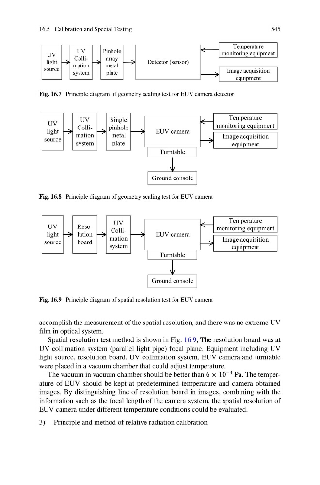
Fig. 16.7 Principle diagram of geometry scaling test for EUV camera detector
EUV camera
Ground console
Turntable
Image acquisition
equipment
Temperature
monitoring equipment
UV
light
source
UV
Collimation
system
Single
pinhole
metal
plate
Fig. 16.8 Principle diagram of geometry scaling test for EUV camera
EUV camera
Ground console
Turntable
Image acquisition
equipment
Temperature
monitoring equipment
UV
light
source
Resolution
board
UV
Collimation
system
Fig. 16.9 Principle diagram of spatial resolution test for EUV camera
accomplish the measurement of the spatial resolution, and there was no extreme UV
film in optical system.
Spatial resolution test method is shown in Fig. 16.9, The resolution board was at
UV collimation system (parallel light pipe) focal plane. Equipment including UV
light source, resolution board, UV collimation system, EUV camera and turntable
were placed in a vacuum chamber that could adjust temperature.
The vacuum in vacuum chamber should be better than 6 × 10
−4 Pa. The temperature of EUV should be kept at predetermined temperature and camera obtained
images. By distinguishing line of resolution board in images, combining with the
information such as the focal length of the camera system, the spatial resolution of
EUV camera under different temperature conditions could be evaluated.
3) Principle and method of relative radiation calibration
545
Detector (sensor)
Image acquisition
equipment
Temperature
monitoring equipment
UV
light
source
UV
Collimation
system
Pinhole
array
metal
plate
Fig. 16.7 Principle diagram of geometry scaling test for EUV camera detector
EUV camera
Ground console
Turntable
Image acquisition
equipment
Temperature
monitoring equipment
UV
light
source
UV
Collimation
system
Single
pinhole
metal
plate
Fig. 16.8 Principle diagram of geometry scaling test for EUV camera
EUV camera
Ground console
Turntable
Image acquisition
equipment
Temperature
monitoring equipment
UV
light
source
Resolution
board
UV
Collimation
system
Fig. 16.9 Principle diagram of spatial resolution test for EUV camera
accomplish the measurement of the spatial resolution, and there was no extreme UV
film in optical system.
Spatial resolution test method is shown in Fig. 16.9, The resolution board was at
UV collimation system (parallel light pipe) focal plane. Equipment including UV
light source, resolution board, UV collimation system, EUV camera and turntable
were placed in a vacuum chamber that could adjust temperature.
The vacuum in vacuum chamber should be better than 6 × 10
−4 Pa. The temperature of EUV should be kept at predetermined temperature and camera obtained
images. By distinguishing line of resolution board in images, combining with the
information such as the focal length of the camera system, the spatial resolution of
EUV camera under different temperature conditions could be evaluated.
3) Principle and method of relative radiation calibration