

13.4 Application of Special Measurement Technology
441
Measure common points
in optical cubic prism
reference coordinate
system with theodolite
Measure common points
with laser tracker
system for coordinate
transformation
Measure points cloud on
antenna end surface
with laser tracker
system
Fit the normal
direction of antenna
end surface
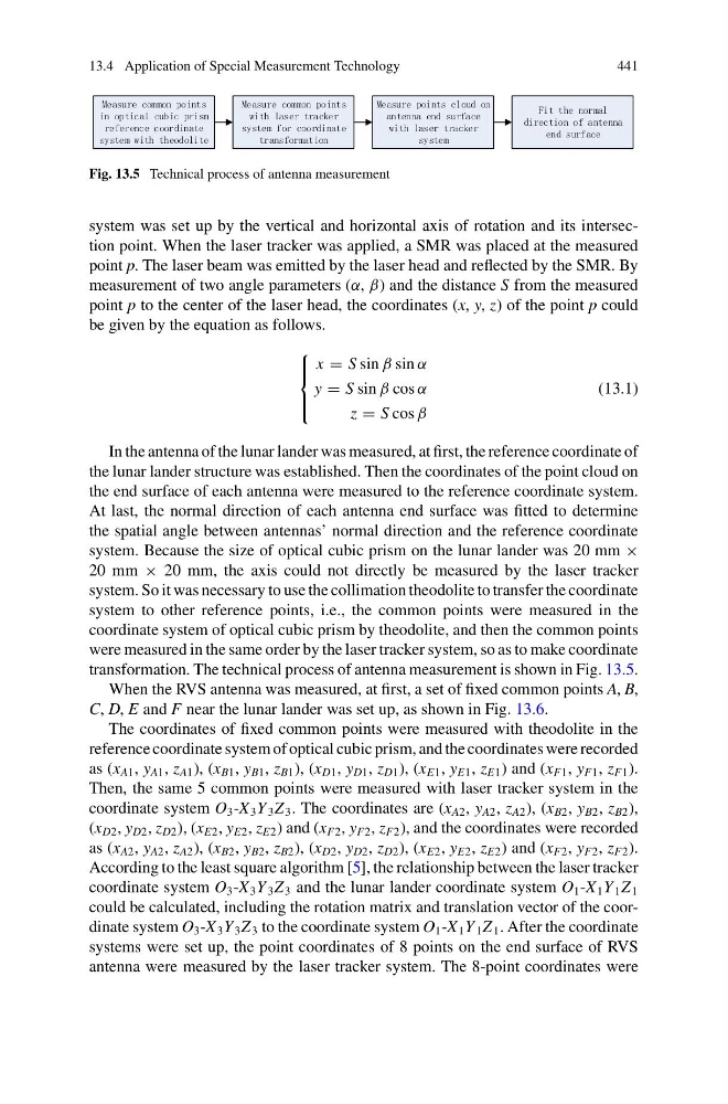
Fig. 13.5 Technical process of antenna measurement
system was set up by the vertical and horizontal axis of rotation and its intersection point. When the laser tracker was applied, a SMR was placed at the measured
point p. The laser beam was emitted by the laser head and reflected by the SMR. By
measurement of two angle parameters (α, β) and the distance S from the measured
point p to the center of the laser head, the coordinates (x, y, z) of the point p could
be given by the equation as follows.
⎧
⎪ ⎨
⎪ ⎩
x = S sin β sin α
y = S sin β cos α
z = S cos β
(13.1)
In the antenna of the lunar lander was measured, at first, the reference coordinate of
the lunar lander structure was established. Then the coordinates of the point cloud on
the end surface of each antenna were measured to the reference coordinate system.
At last, the normal direction of each antenna end surface was fitted to determine
the spatial angle between antennas’ normal direction and the reference coordinate
system. Because the size of optical cubic prism on the lunar lander was 20 mm ×
20 mm × 20 mm, the axis could not directly be measured by the laser tracker
system. So it was necessary to use the collimation theodolite to transfer the coordinate
system to other reference points, i.e., the common points were measured in the
coordinate system of optical cubic prism by theodolite, and then the common points
were measured in the same order by the laser tracker system, so as to make coordinate
transformation. The technical process of antenna measurement is shown in Fig. 13.5.
When the RVS antenna was measured, at first, a set of fixed common points A, B,
C, D, E and F near the lunar lander was set up, as shown in Fig. 13.6.
The coordinates of fixed common points were measured with theodolite in the
reference coordinate system of optical cubic prism, and the coordinates were recorded
as (x A1 , y A1 , z A1 ), (x B1 , y B1 , z B1 ), (x D1 , y D1 , z D1 ), (x E1 , y E1 , z E1 ) and (x F1 , y F1 , z F1 ).
Then, the same 5 common points were measured with laser tracker system in the
coordinate system O 3 -X 3 Y 3 Z 3 . The coordinates are (x A2 , y A2 , z A2 ), (x B2 , y B2 , z B2 ),
(x D2 , y D2 , z D2 ), (x E2 , y E2 , z E2 ) and (x F2 , y F2 , z F2 ), and the coordinates were recorded
as (x A2 , y A2 , z A2 ), (x B2 , y B2 , z B2 ), (x D2 , y D2 , z D2 ), (x E2 , y E2 , z E2 ) and (x F2 , y F2 , z F2 ).
According to the least square algorithm [5], the relationship between the laser tracker
coordinate system O 3 -X 3 Y 3 Z 3 and the lunar lander coordinate system O 1 -X 1 Y 1 Z 1
could be calculated, including the rotation matrix and translation vector of the coordinate system O 3 -X 3 Y 3 Z 3 to the coordinate system O 1 -X 1 Y 1 Z 1 . After the coordinate
systems were set up, the point coordinates of 8 points on the end surface of RVS
antenna were measured by the laser tracker system. The 8-point coordinates were
441
Measure common points
in optical cubic prism
reference coordinate
system with theodolite
Measure common points
with laser tracker
system for coordinate
transformation
Measure points cloud on
antenna end surface
with laser tracker
system
Fit the normal
direction of antenna
end surface
Fig. 13.5 Technical process of antenna measurement
system was set up by the vertical and horizontal axis of rotation and its intersection point. When the laser tracker was applied, a SMR was placed at the measured
point p. The laser beam was emitted by the laser head and reflected by the SMR. By
measurement of two angle parameters (α, β) and the distance S from the measured
point p to the center of the laser head, the coordinates (x, y, z) of the point p could
be given by the equation as follows.
⎧
⎪ ⎨
⎪ ⎩
x = S sin β sin α
y = S sin β cos α
z = S cos β
(13.1)
In the antenna of the lunar lander was measured, at first, the reference coordinate of
the lunar lander structure was established. Then the coordinates of the point cloud on
the end surface of each antenna were measured to the reference coordinate system.
At last, the normal direction of each antenna end surface was fitted to determine
the spatial angle between antennas’ normal direction and the reference coordinate
system. Because the size of optical cubic prism on the lunar lander was 20 mm ×
20 mm × 20 mm, the axis could not directly be measured by the laser tracker
system. So it was necessary to use the collimation theodolite to transfer the coordinate
system to other reference points, i.e., the common points were measured in the
coordinate system of optical cubic prism by theodolite, and then the common points
were measured in the same order by the laser tracker system, so as to make coordinate
transformation. The technical process of antenna measurement is shown in Fig. 13.5.
When the RVS antenna was measured, at first, a set of fixed common points A, B,
C, D, E and F near the lunar lander was set up, as shown in Fig. 13.6.
The coordinates of fixed common points were measured with theodolite in the
reference coordinate system of optical cubic prism, and the coordinates were recorded
as (x A1 , y A1 , z A1 ), (x B1 , y B1 , z B1 ), (x D1 , y D1 , z D1 ), (x E1 , y E1 , z E1 ) and (x F1 , y F1 , z F1 ).
Then, the same 5 common points were measured with laser tracker system in the
coordinate system O 3 -X 3 Y 3 Z 3 . The coordinates are (x A2 , y A2 , z A2 ), (x B2 , y B2 , z B2 ),
(x D2 , y D2 , z D2 ), (x E2 , y E2 , z E2 ) and (x F2 , y F2 , z F2 ), and the coordinates were recorded
as (x A2 , y A2 , z A2 ), (x B2 , y B2 , z B2 ), (x D2 , y D2 , z D2 ), (x E2 , y E2 , z E2 ) and (x F2 , y F2 , z F2 ).
According to the least square algorithm [5], the relationship between the laser tracker
coordinate system O 3 -X 3 Y 3 Z 3 and the lunar lander coordinate system O 1 -X 1 Y 1 Z 1
could be calculated, including the rotation matrix and translation vector of the coordinate system O 3 -X 3 Y 3 Z 3 to the coordinate system O 1 -X 1 Y 1 Z 1 . After the coordinate
systems were set up, the point coordinates of 8 points on the end surface of RVS
antenna were measured by the laser tracker system. The 8-point coordinates were